
Accumulating element module

a technology of accumulating elements and modules, applied in the direction of cell components, primary cell maintainance/servicing, coupling device connections, etc., can solve the problems of poor ability to assemble temperature detectors, increased manufacturing costs, and generation of additional and undesirable stress in accumulating elements, so as to inhibit the disengagement of caps, prevent the generation of additional stress, and improve the workability of adhesion

Inactive Publication Date: 2005-07-26
HONDA MOTOR CO LTD
View PDF6 Cites 25 Cited by
  • Summary
  • Abstract
  • Description
  • Claims
  • Application Information

AI Technical Summary

Benefits of technology

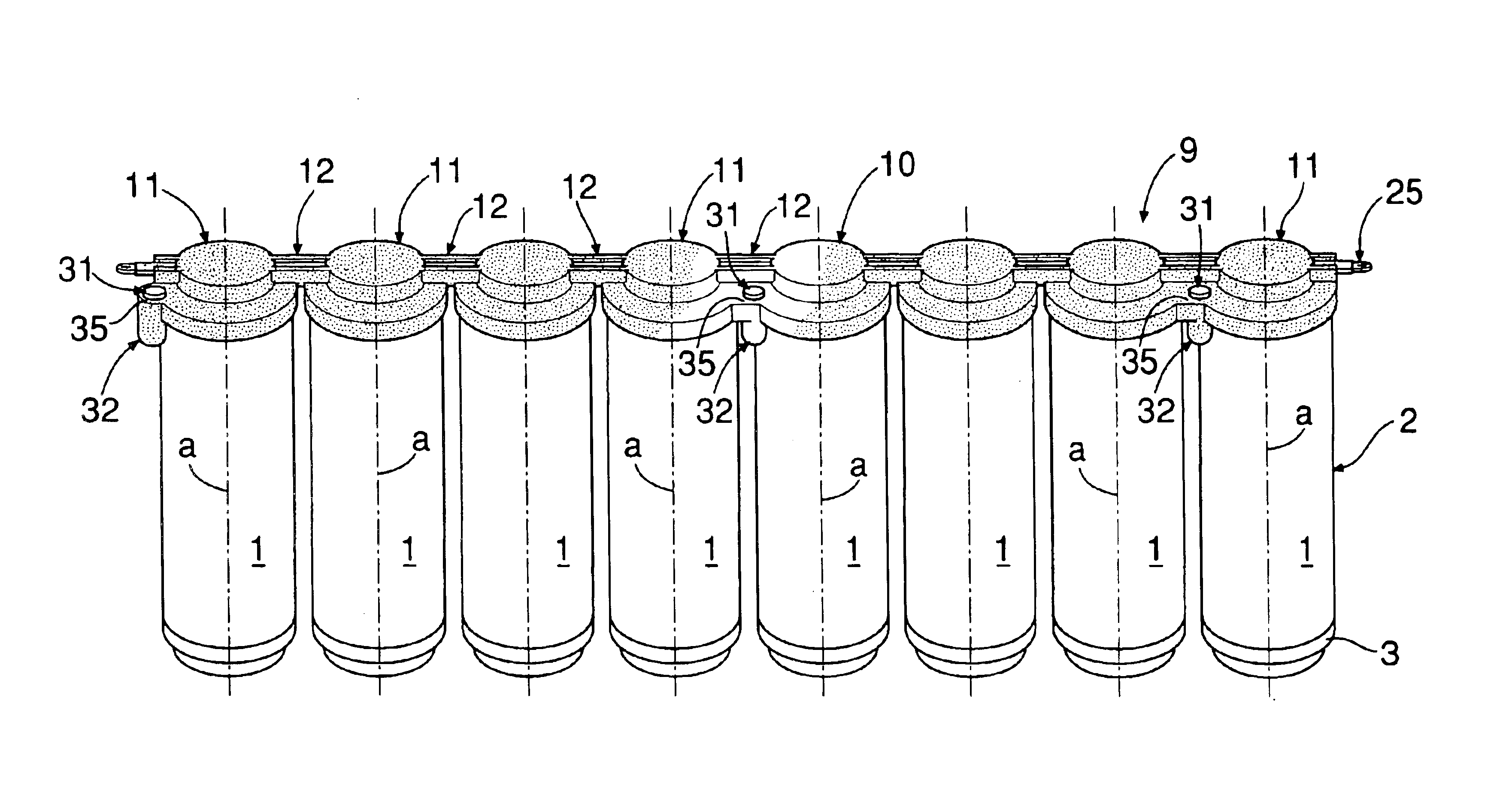
The present invention provides an accumulating element module that reduces stress on the accumulating elements caused by the connection structure of the other end of the accumulating elements. The module includes a plurality of accumulating elements arranged in a row, connected at their other ends by an insulating connecting member. A temperature detector is provided in each accumulating element to detect high temperatures. The insulating connecting member is made of elastic material and includes caps and connectors to connect the accumulating elements together. A deformation-resistant, band-shaped temperature sensing member is inserted through the caps and includes flat temperature detectors and metal plates to electrically connect the detectors. The accumulating elements can be moved individually, and the temperature detectors are assembled with the accumulating elements without increasing the space occupied by the module.

Problems solved by technology

Therefore, when the insulating connecting member vibrates, additional and undesirable stress is generated in the accumulating element.
When using tape to employ the conventional method of mounting, the ability to assemble the temperature detector is poor.
Also, when the special fixing member is used, manufacturing costs increase and a space occupied by the accumulating element module is enlarged.

Method used


Image

  • Accumulating element module
  • Accumulating element module
  • Accumulating element module

Examples


Embodiment Construction

[0029]The present invention will now be described by way of a preferred embodiment with reference to the accompanying drawings.

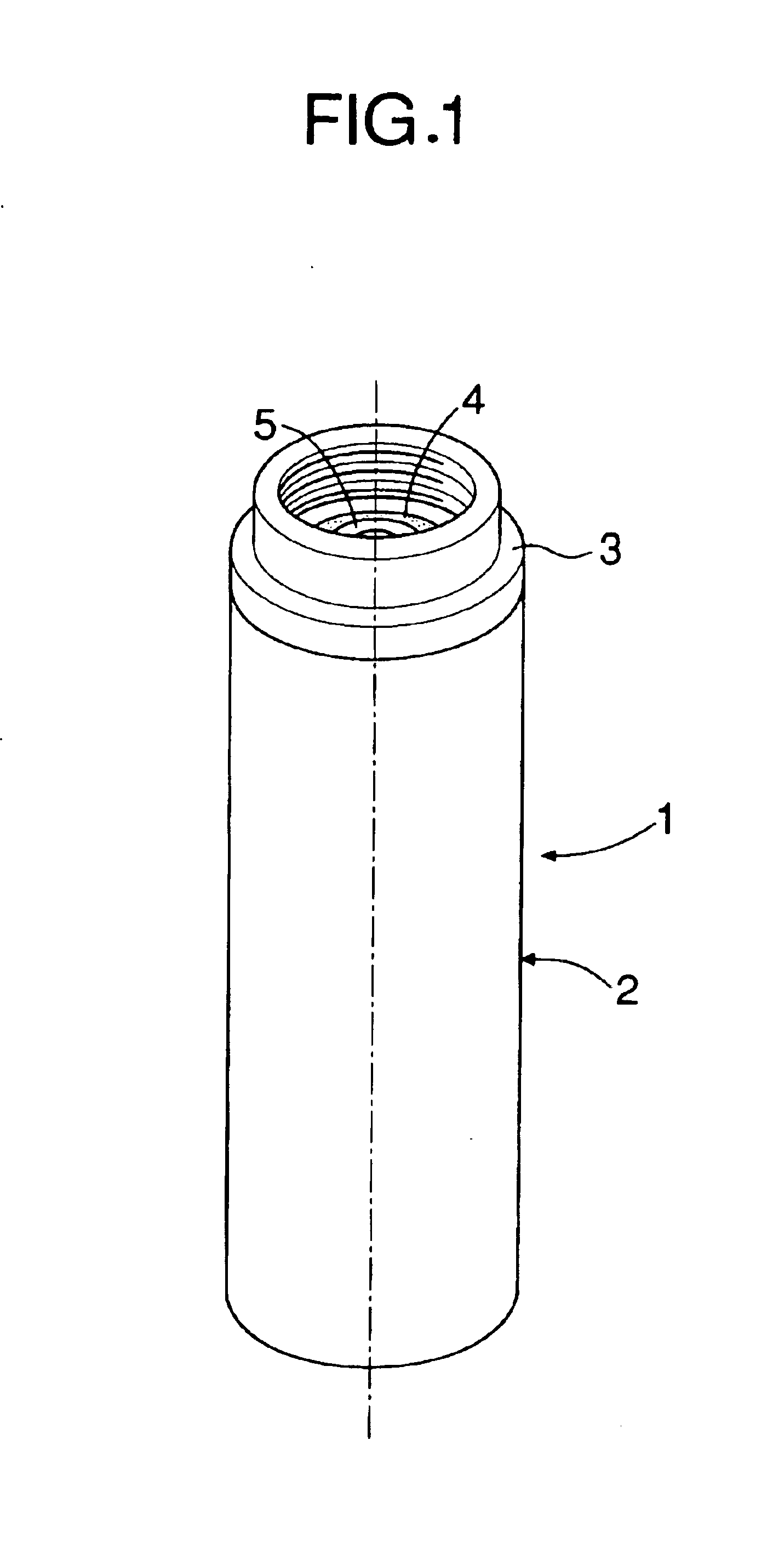
[0030]As shown in FIG. 1, an electric double-layer capacitor accumulating element 1 includes a cylindrical vessel 2 made of aluminum alloy. A positive pole and a negative pole are insulated and cylindrically wound within the vessel 2. A portion of a cylinder 3, which is made of an aluminum alloy, is fitted and welded in an opening provided at one end of the vessel 2. The vessel 2 and the cylinder 3 function as negative pole terminals. A positive pole terminal 5 is retained on an inner peripheral surface of the cylinder 3 on a side of the vessel 2 with an annular insulator 4, which is made of a synthetic resin interposed therebetween.

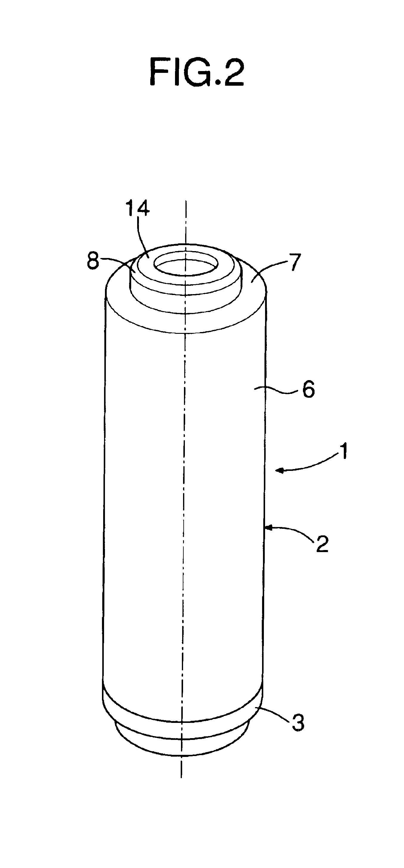
[0031]As shown in FIG. 2, the other end of the vessel 2 is provided with an annular stepped face 7, which faces inward and is connected to a larger-diameter main body 6 of the vessel 2. A smaller-diameter annular projection 8 pro...


PUM

PropertyMeasurementUnit
elastic insulatingaaaaaaaaaa
temperatureaaaaaaaaaa
diameteraaaaaaaaaa

Abstract

An accumulating element module includes a plurality of accumulating elements, each having a positive pole terminal and a negative pole terminal at one end. The accumulating elements are connected together at their other ends by an insulating connecting member made of a synthetic rubber. The insulating connecting member includes a plurality of caps and connectors. A deformation-resistant, band-shaped, temperature sensing member having a plurality of excessively raised temperature detectors is inserted through the caps.

Description

BACKGROUND OF THE INVENTION[0001]1. Field of the Invention[0002]The present invention relates to an accumulating element module, and particularly to an accumulating element module including a plurality of accumulating elements arranged in a row with their respective axes parallel to one another. Each accumulating element has a cylindrical shape with a positive pole terminal and a negative pole terminal at one end. The accumulating elements are connected at their respective other ends to one another by an insulating connecting member. A temperature detector which detects an extremely high or, excessively raised, temperature is provided in each accumulating element. An electric double-layer capacitor, a secondary battery, and the like are encompassed by the accumulating element.[0003]2. Description of the Related Art[0004]A known insulating connecting member includes a hard plate made of a synthetic resin and a plurality of mounting portions, which include a plurality of retaining pie...

Claims


Application Information

Patent Timeline
Patent Type & Authority Patents(United States)
IPC IPC(8): H01G2/00H01G9/00H01G2/14H01G5/00H01G9/26H01G5/38H01M2/10H01R24/00H01M6/50H01M10/42
CPCH01M6/5011H01M6/5038H01M10/4207Y02E60/10
Inventor KUBOTA, SHINYAMITA, YOSHINORIYAMAMOTO, KOICHI
Owner HONDA MOTOR CO LTD
Learn More