Glass composition, protective-layer composition, binder composition, and lamp
a technology of protective layer and composition, applied in the field of glass composition, protective layer composition, binder composition, lamp, can solve the problem of increasing the demand for performance capabilities in the recent past, and achieve the effect of improving the luminous efficiency of lamps
- Summary
- Abstract
- Description
- Claims
- Application Information
AI Technical Summary
Benefits of technology
Problems solved by technology
Method used
Image
Examples
embodiment 1
[Embodiment 1]
[0071]FIG. 1 is a side view (partially sectioned) of a straight type fluorescent lamp. FIG. 2 is a schematic view showing light emission mechanism of the fluorescent lamp.
[0072]As shown in FIG. 1, a fluorescent lamp 10 is composed of a tubular glass tube 11 provided with a cap 16 fixedly attached to each end.
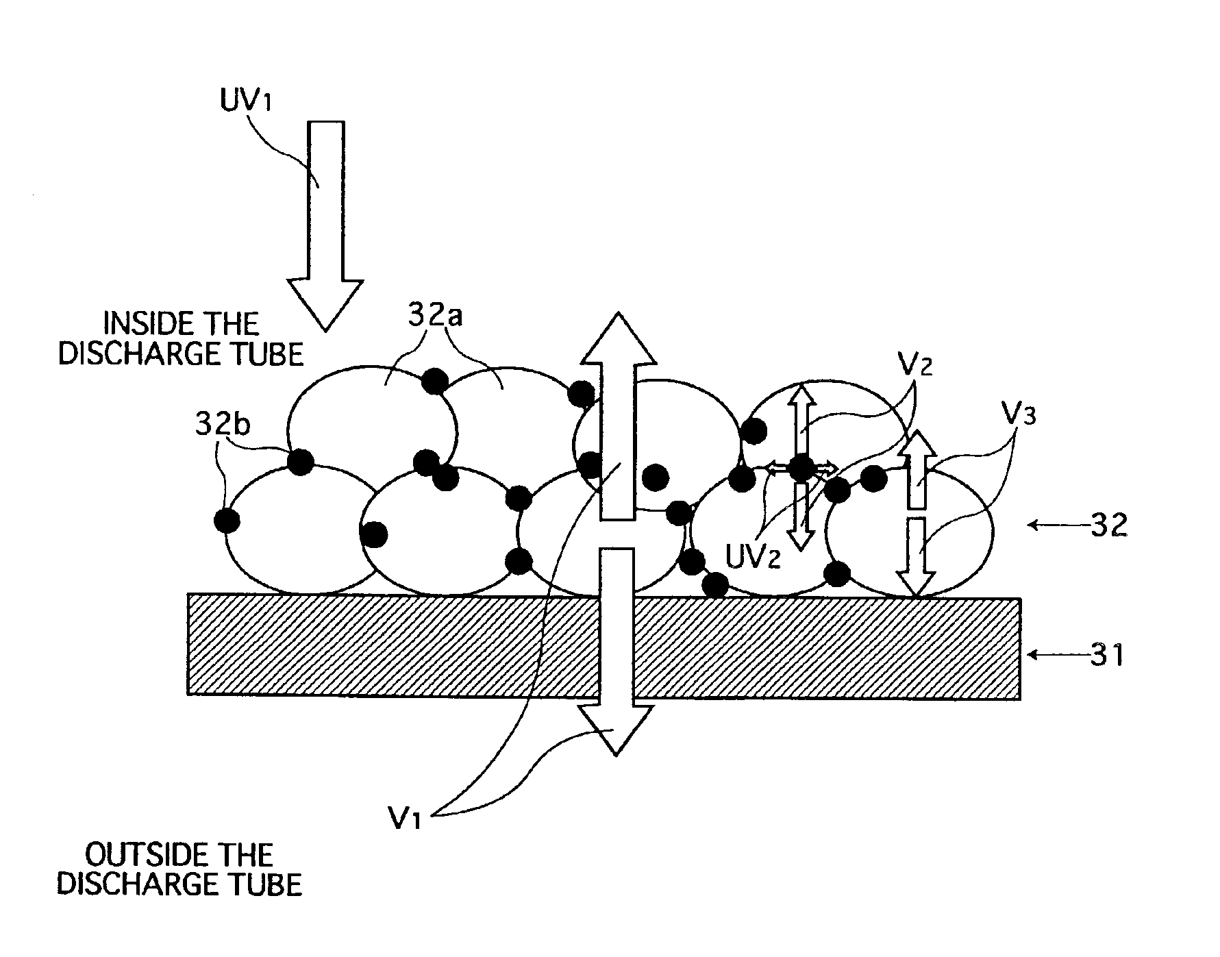
[0073]As shown in the cross-sectional part in FIG. 1, a protective layer 12 is formed on the inner surface of the glass tube 11, and a phosphor layer 13 is formed on the protective layer 12. A discharge space 14 enclosed with the phosphor layer 13 is filled with a rare gas such as argon together with mercury. The sealing pressure is within a range of 2-4 hPa, for example.
[0074]The glass tube 11 is formed of a material mainly containing soda glass. The material also contains a rare-earth oxide, which will be described later.
[0075]The protective layer 12 is a layer mainly composed of an oxide selected from SiO2, α-Al2O3, γ-Al2O3, TiO2, ZnO, B2O3, Sc2O3, Y2O3, MgO, an...
embodiment 2
[Embodiment 2]
[0145]A fluorescent lamp according to an embodiment 2 of the present invention is basically similar in construction to the fluorescent lamp 10 of the embodiment 1. The difference lies in the composition of the glass tube 11 and the composition of the electrode glass. Hereinafter, description of the present embodiment is given mainly to the difference.
[0146]The glass tube 11 employed in the present embodiment is manufactured from the glass composition containing the following components.
[0147]SiO2: 68.5 wt %
[0148]Al2O3: 2.0 wt %
[0149]R2O: 14.0 wt % (where R is at least one element selected from Li, Na, and K)
[0150]R′O: 10.0 wt % (where R′ is at least one element selected from Mg, Ca, Sr, Ba, and Zn)
[0151]Eu2O3: 5.5 wt %
[0152]The electrode glass 17 is manufactured from the glass composition containing the following components.
[0153]SiO2: 62.5 wt %
[0154]Al2O3: 1.0 wt %
[0155]R2O: 7.5 wt % (where R is at least one element selected from Li, Na, and K)
[0156]R′O: 5.5 wt % (whe...
embodiment 3
[Embodiment 3]
[0177]Now, description is given to a fluorescent lamp 20 according to an embodiment 3 of the present invention with reference to FIG. 5.
[0178]As shown in FIG. 5, the fluorescent lamp 20 is basically similar in construction to the fluorescent lamp 10 according to the embodiment 1. Unlike the fluorescent lamp 10, however, the inner surface of a protective layer 22 is not covered with a phosphor layer. Preferably, the thickness of the protective layer 22 is within a range of 0.01-1 μm.
[0179]The protective layer 22 contains a rare-earth oxide. Specifically, the protective layer 22 contains, as a main component, at least one selected from SiO2, α-Al2O3, γ-Al2O3, TiO2, ZnO, B2O3, Sc2O3, Y2O3, MgO, and Cs2O. Additionally, the protective layer contains M2O3 (where M is at least one selected from Pr, Nd, Eu, Gd, Tb, and Dy) in an amount of 0.01 to 30 wt %.
[0180]In the figure, the same references are used to denote parts similar to those of the fluorescent lamp 10. Description o...
PUM
| Property | Measurement | Unit |
|---|---|---|
| wavelength | aaaaa | aaaaa |
| pressure | aaaaa | aaaaa |
| pressure | aaaaa | aaaaa |
Abstract
Description
Claims
Application Information
 - R&D
- Intellectual Property
- Life Sciences
- Materials
- Tech Scout
- Unparalleled Data Quality
- Higher Quality Content
- 60% Fewer Hallucinations
Browse by: Latest US Patents, China's latest patents, Technical Efficacy Thesaurus, Application Domain, Technology Topic, Popular Technical Reports.
© 2025 PatSnap. All rights reserved.Legal|Privacy policy|Modern Slavery Act Transparency Statement|Sitemap|About US| Contact US: help@patsnap.com


