
Method of forming metal blanks for sputtering targets

a metal blank and target technology, applied in the field of forming metal blanks, can solve the problems of excessive cost of process, excessive amount of low-value grinding scrap called swarf, and significant difficulties in achieving the effect of cost-effective metal products and avoiding the costs of time, labor and lost metal materials

Inactive Publication Date: 2005-07-26
GLOBAL ADVANCED METALS USA
View PDF15 Cites 7 Cited by
  • Summary
  • Abstract
  • Description
  • Claims
  • Application Information

AI Technical Summary

Benefits of technology

[0008]A feature of the present invention is to provide a method to manufacture cost-effective metal products. The present invention relates to avoiding the costs associated with time, labor, and lost metal material, which incurs during the grinding of both surfaces of a metal planar object.
[0009]Another feature of the present invention is to modify the tolerances of the tantalum or other metal target blanks to thereby enhance production of the metal blank, disc, and the sputtering target.

Problems solved by technology

In the field of metal fabrication in general, and sputtering targets in particular, significant difficulties arise with regard to the costs associated with producing planar discs with very highly specific dimensional requirements.
However, achieving such stringent tolerances in gauge and flatness requires the grinding and the lapping of the blanks, a process which is prohibitively expensive and generates excessive amounts of low-value grinding scrap called swarf.
Typically, the value of the tantalum contained in the swarf is less than the value of tantalum turnings generated by machining operations since it is often difficult and expensive to separate the tantalum particles from the grinding media comprising the swarf, and because of the greater propensity for contamination of the tantalum by grinding compared to machining.

Method used


Image

  • Method of forming metal blanks for sputtering targets
  • Method of forming metal blanks for sputtering targets
  • Method of forming metal blanks for sputtering targets

Examples


example 1

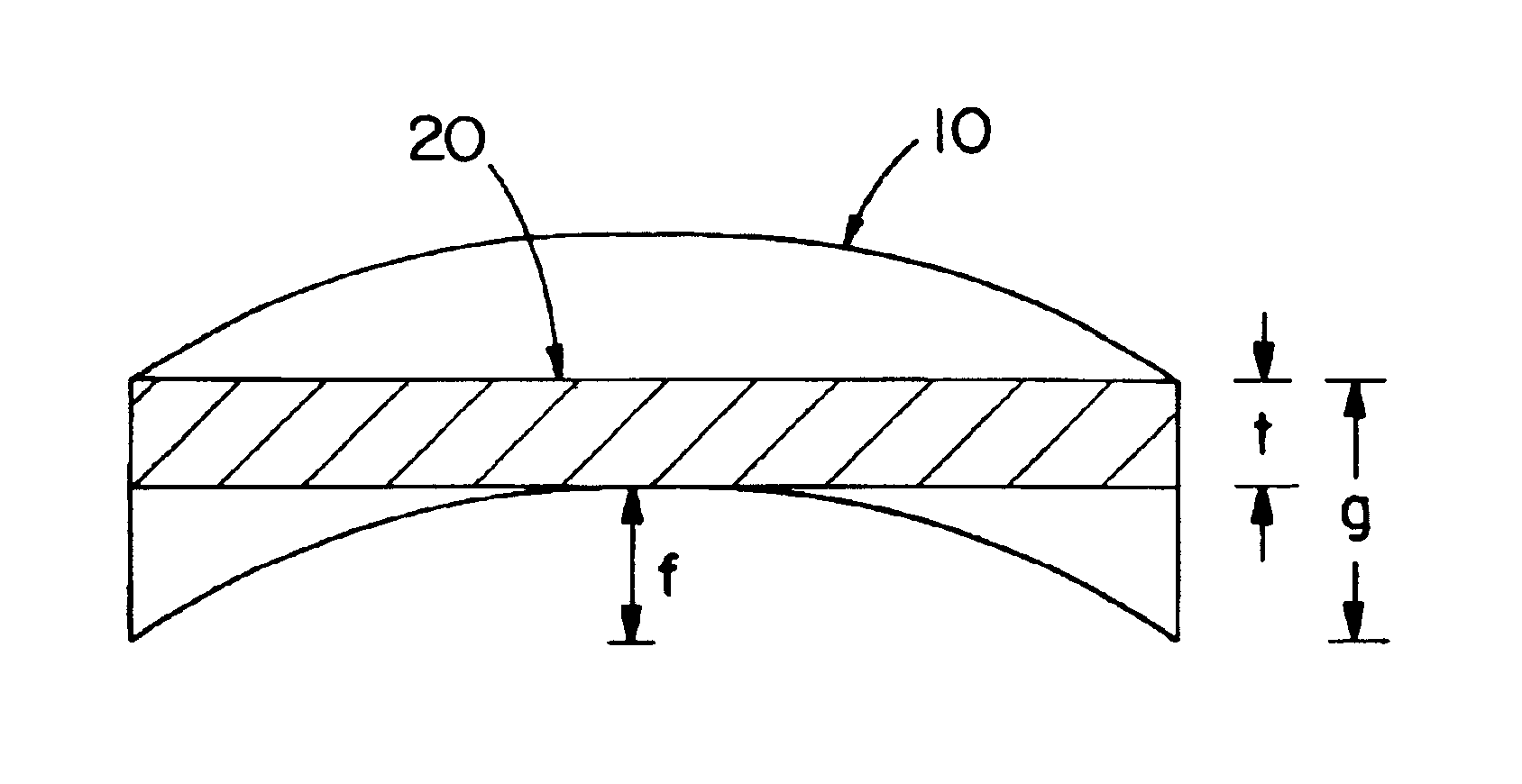
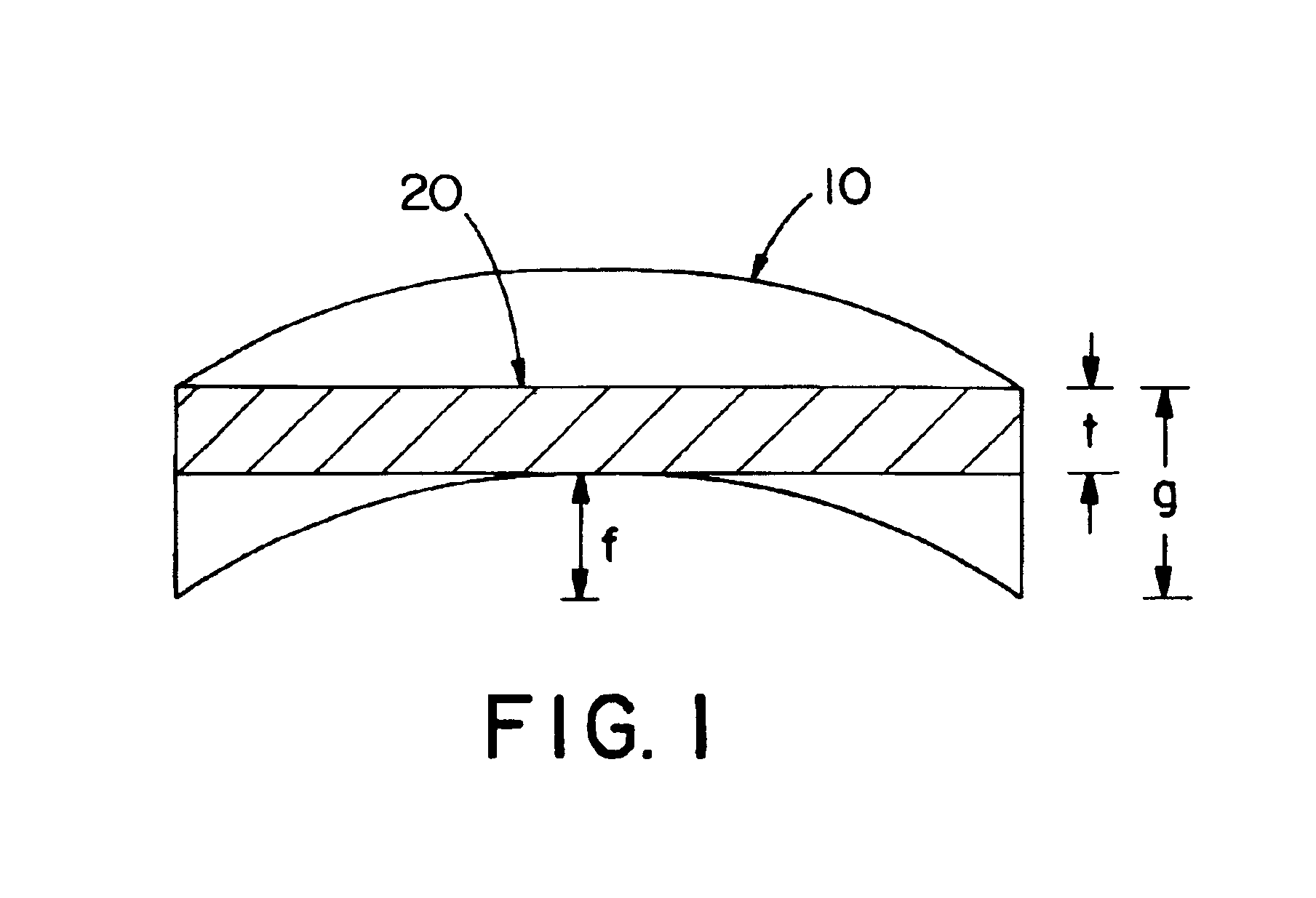
[0058]FIG. 1 shows a rolled metal plate (10) having an as-rolled or as-level-rolled flatness designated “f” and an initialized gauge thickness of “g.” A planar sputtering target (20) of finished thickness “t” can be produced. Generally, the relationship between initial thickness with respect to initial flatness and finished thickness is

g=t+(2f+0.005″)

[0059]The amount of scrap generated in producing a target 20 from plate 10 can be calculated using the following formula:

Vs=(2f+0.005″)·AT·ρTa AT=target area ρTa=0.060 lbs / in3

and the scrap credit can be calculated using the following formula:

Cs=Vs (Ms) Ms=marked value of scrap Vs=volume of scrap Cs=Scrap credit

[0060]Consider the manufacturing costs of a tantalum blank 14″ in diameter (154 in2) and 0.250″ thick, and standard plate manufacturing cost (Cst) of $250 / lb.

[0061]Case 1 Double disc grinding of as level rolled blanks to 0.005″ flat[0062]Assume: initial flatness f=0.075″[0063]grinding cost=Cgm=$50 per disc[0064]grinding swarf valu...


PUM

PropertyMeasurementUnit
flatnessaaaaaaaaaa
flatnessaaaaaaaaaa
flatnessaaaaaaaaaa

Abstract

The present invention relates to an improvement in the manufacture of metal blanks, discs, and sputtering targets by flattening only one of the two surfaces of a metal plate. The elimination of flattening the metal plate's second surface results in a significant cost reduction. The metal plate of the present invention preferably has a single-side flatness of 0.005 inches or less, which improves the reliability of the bond between the target blank and a backing plate. Preferred metals include, but are not limited to, tantalum, niobium, titanium, and alloys thereof. The present invention also relates to machining the first side of a metal plate, bonding the first side to a backing plate, and then optionally machining the second side of the metal plate.

Description

BACKGROUND OF THE INVENTION[0001]The present invention relates to a method for making sputtering targets that reduces machine costs and improves quality and reliability, relative to conventional methods for preparing sputtering targets. The present invention further relates to methods of preparing improved metal discs. The present invention also relates to a method for reducing the manufacturing costs of sputtering targets and / or metal discs.[0002]In the field of metal fabrication in general, and sputtering targets in particular, significant difficulties arise with regard to the costs associated with producing planar discs with very highly specific dimensional requirements. It is common practice in the field of manufacturing a metal disc to flatten both sides of a metal blank which is eventually formed into a metal disc, for example, a tantalum sputtering target preform. This requires the grinding of both sides of the metal blank, rolling both sides, or press flattening and / or surfa...

Claims


Application Information

Patent Timeline
Patent Type & Authority Patents(United States)
IPC IPC(8): C23C14/34C22F1/00
CPCC22F1/00C23C14/3407B24B1/00C23C14/3414
Inventor MICHALUK, CHRISTOPHER A.
Owner GLOBAL ADVANCED METALS USA
Learn More