
Magnetic flow meter with reference electrode

a reference electrode and flow meter technology, applied in the direction of liquid/fluent solid measurement, instruments, volume/mass flow by differential pressure, etc., can solve the problems of corrosion of ground ring or ground electrode, non-conductive piping, and electrical contact with process piping itself not establishing a reference to process fluid, etc., to achieve the effect of reducing flow

Active Publication Date: 2005-07-26
MICRO MOTION INC
View PDF376 Cites 40 Cited by
  • Summary
  • Abstract
  • Description
  • Claims
  • Application Information

AI Technical Summary

Benefits of technology

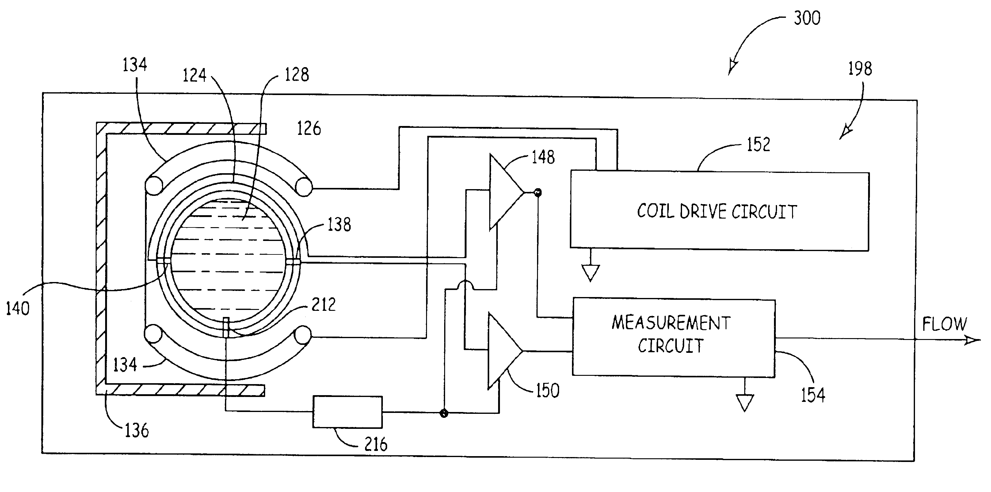
[0007]A magnetic flow meter includes circuitry that is adapted to be electrically coupled to a process fluid. A reference contact is configured to contact the process fluid flowing within a flowtube. An electrical component is provided in series between the reference contact and the circuitry to reduce the flow of electrical current through the reference contact.

Problems solved by technology

The connection between the ground electrode and flowtube through bolts or some other means can provide a path for electrical current to ground which may lead to corrosion of the ground ring or ground electrode.
However, in some applications, the process piping itself may be non-conductive, or may have a non-conductive inner lining.
Thus, electrical contact to the process piping itself will not establish a reference to the process fluid.
One of the problems that has occurred in magnetic flow meters in accordance with the prior art is significant corrosion of ground electrodes.
The connection between the ground electrode and flowtube through bolts or some other means can provide a path for electrical connection to ground which may lead to corrosion of the ground ring or ground electrode.
While this approach has generally resolved many problems, it has not addressed all situations.
Some situations continue to exist where it is not feasible to isolate the flowtube from ground due to the particular application.
However, this will likely provide some path to earth resulting in stray current corrosion of the ground electrode or ground ring.
However, in some situations, ground rings are impractical.
For example, the failure of a ground ring can result in leaking of the process fluid.
Further, the use of an inert metal such as platinum is expensive.

Method used


Image

  • Magnetic flow meter with reference electrode
  • Magnetic flow meter with reference electrode
  • Magnetic flow meter with reference electrode

Examples


Embodiment Construction

[0012]A magnetic flow meter is disclosed that provides increased ground electrode corrosion resistance in response to stray currents present in the process. In particular, embodiments of the present invention act to limit, or other inhibit, stray currents present in some process installations from flowing through the ground electrode to ground.

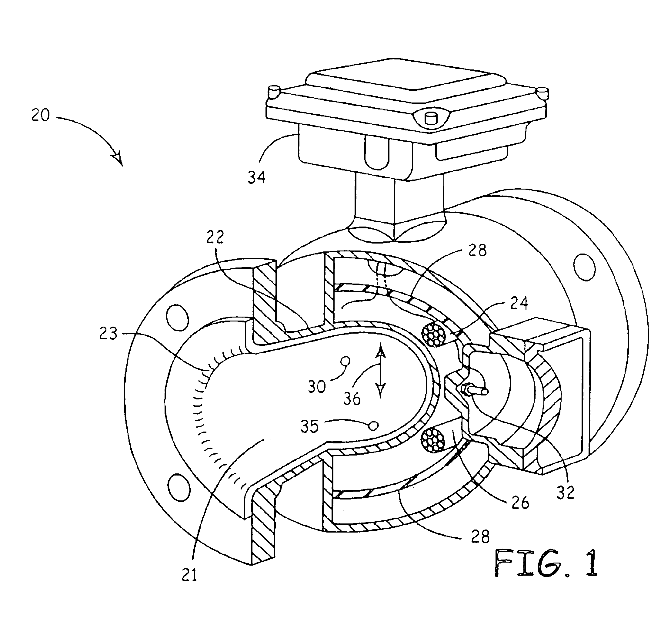
[0013]FIG. 1 is a partially cut away view of an embodiment of a magnetic flow meter in which embodiments of the present invention are particularly useful. Magnetic flow meter 20 includes a flowtube 22 formed of low magnetic permeability material with an electrically insulating liner 23, an electromagnet 26 is formed by a coil, a ferromagnetic core or shield 28 and electrodes 30, 32. The electromagnet 26 and the electrodes 30, 32 are wired to a transmitter circuit 34 as is ground electrode 35. In operation, the transmitter circuit 34 drives the electromagnet 26 with an electrical current, and the electromagnet 26 produces a magnetic field 36 in...


PUM


Abstract

An magnetic flow meter is provided which includes a reference electrode configured to electrically couple process fluid flowing within a flowtube of the flow meter. The reference electrode is adapted to measure potential of the process fluid. A current limiter is configured to limit current flow through the reference electrode and thereby reduce corrosion of the reference electrode.

Description

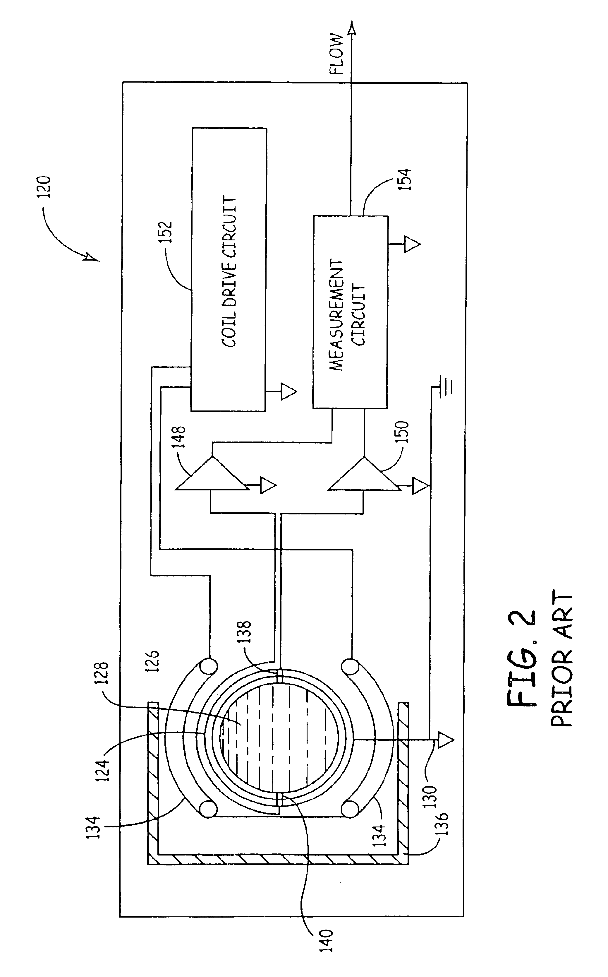
FIELD OF THE INVENTION[0001]The present invention is related to the process measurement and control industry. More specifically, the present invention is related to magnetic flow meters.BACKGROUND OF THE INVENTION[0002]Magnetic flow meters are used to measure flow of a conductive process fluid through a flowtube. The conductive fluid flows past an electromagnet and electrodes. In accordance with Faraday's law of electromagnetic induction, an electromotive force (EMF) is induced in the fluid due to an applied magnetic field. The EMF is proportional to the flow rate of the fluid. The electrodes are positioned in the flowtube to make electrical contact with the flowing fluid. The electrodes sense the EMF that is magnetically induced in the fluid which can then be used to determine flow rate. The EMF is measured by the flow meter using a differential front end amplifier connected across the electrodes. The potential of the process fluid is used as a reference for the differential amplif...

Claims


Application Information

Patent Timeline
Patent Type & Authority Patents(United States)
IPC IPC(8): G01F1/56G01F1/60G01F1/58
CPCG01F1/584G01F1/60
Inventor SCHULZ, ROBERT K.
Owner MICRO MOTION INC
Learn More