
Ultra-wide band meanderline fed monopole antenna

a monopole antenna and ultra-wide band technology, applied in the structure of elongated active elements, resonant antennas, radiating elements, etc., can solve the problems of insufficient multi-band operation, and insufficient space for conventional quarter and half wavelength antenna elements. , to achieve the effect of improving bandwidth performance and small space requirements

Inactive Publication Date: 2005-07-12
SKYCROSS INC
View PDF9 Cites 32 Cited by
  • Summary
  • Abstract
  • Description
  • Claims
  • Application Information

AI Technical Summary

Benefits of technology

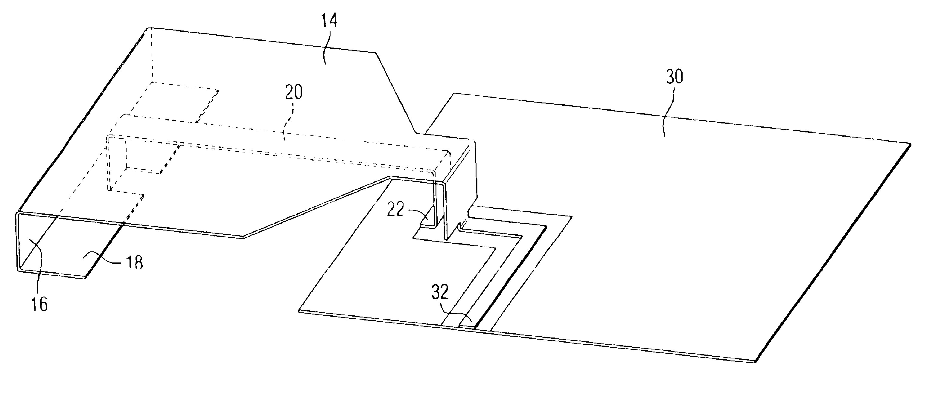
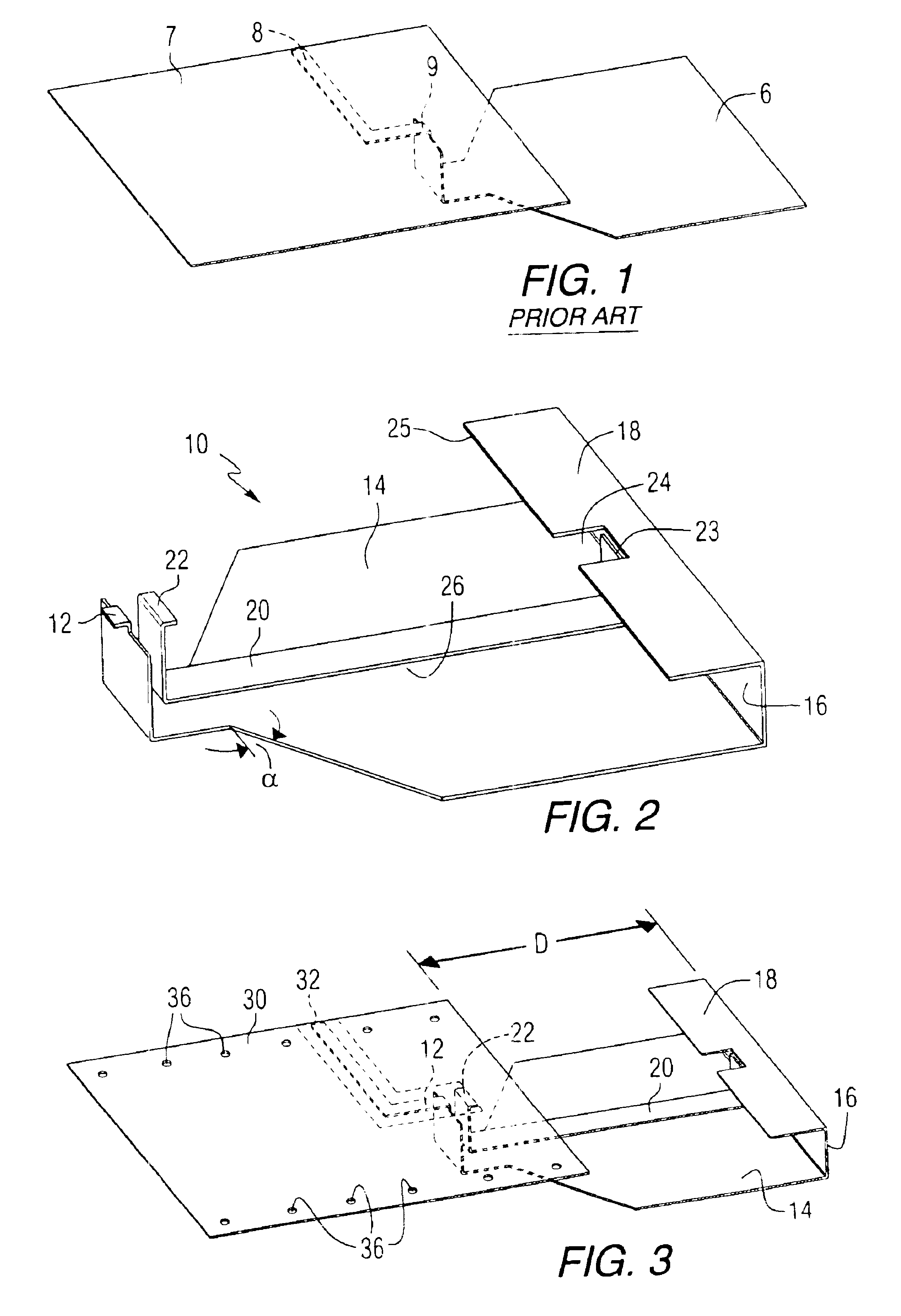
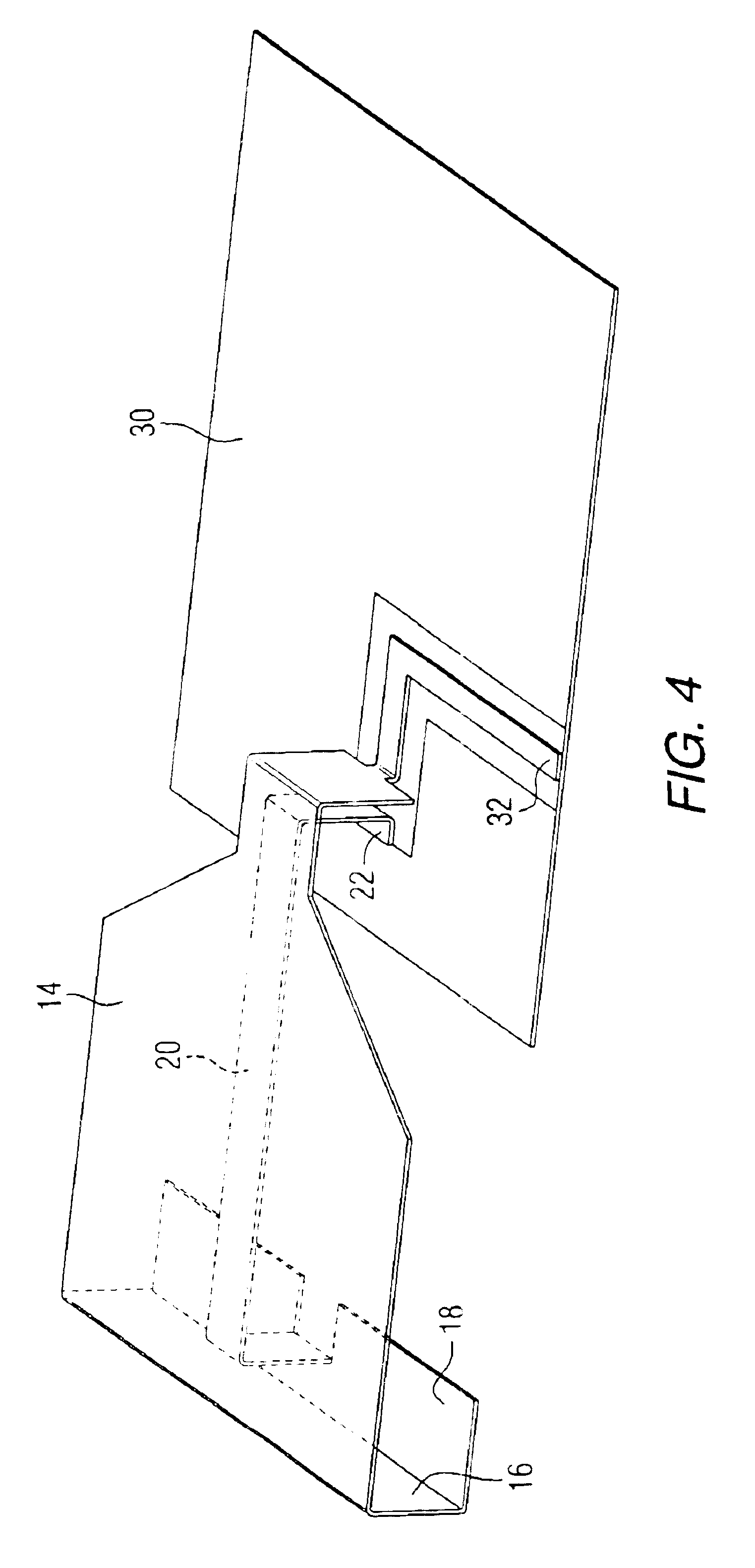
[0023]An antenna according to the teachings of the present invention presents a relatively small space requirement and provides improved bandwidth performance. The antenna comprises top and bottom substantially parallel planar elements wherein the top planar element extends beyond the bottom planar element. A side planar element is disposed substantially perpendicular to and interconnects an edge of the top planar element and an edge of the bottom planar element. A first end of a meanderline conductor is connected to the free edge of the bottom planar element. The meanderline conductor further comprises a second end for connection to a ground plane. An open edge of the top planar element is connected to a source terminal for receiving signals when the antenna is operative in the receiving mode and for supplying signals to be transmitted when the antenna is operative in the transmitting mode.

Problems solved by technology

Smaller packaging of state-of-the-art communications devices may not provide sufficient space for the conventional quarter and half wavelength antenna elements.
However, conventional loop antennas are too large for handset applications and do not provide multi-band operation.
Since the antenna is designed to present a dimension that is a quarter or half wavelength at the operational frequency, when the operational frequency changes, the antenna is no longer operating at a resonant condition and antenna performance deteriorates.
The major drawback of the dipole, when considered for use in personal wireless communications devices, is its size.
Clearly it is difficult to locate such an antenna in the small space envelope associated with today's handheld devices.
Notwithstanding these techniques, it remains difficult to realize an efficient antenna or antenna system that satisfies the multi-band / wide bandwidth operational features in a relatively small physical volume.

Method used


Image

  • Ultra-wide band meanderline fed monopole antenna
  • Ultra-wide band meanderline fed monopole antenna
  • Ultra-wide band meanderline fed monopole antenna

Examples


Embodiment Construction

[0029]Before describing in detail the particular ultra wideband antenna in accordance with the present invention, it should be observed that the present invention resides primarily in a novel combination of elements. Accordingly, the elements have been represented by conventional elements in the drawings, showing only those specific details that are pertinent to the present invention, so as not to obscure the disclosure with structural details that will be readily apparent to those skilled in the art having the benefit of the description herein.

[0030]FIG. 1 illustrates a prior art monopole antenna 6 electrically connected to an disposed overlying a ground plane 7, with a feed conductor 8 connected to a source feed terminal 9 of the antenna 6. The antenna 6 operates as a conventional monopole antenna above a ground plane as described above.

[0031]An antenna constructed according to the teachings of the present invention includes the aforementioned meanderline structures and a pluralit...


PUM


Abstract

An ultra-wide bandwidth antenna. The antenna comprises a serially electrically connected top radiator, side radiator and bottom radiator. Geometrically, the top radiator, side radiator and bottom radiator form a U-shaped structure. A meanderline conductor is connected between the bottom radiator and ground. The top radiator is connected to a signal feed.

Description

[0001]This application claims the benefit of the provisional application filed on Apr. 19, 2002, assigned application No. 60 / 373,865 and entitled, Ultra-wide band meanderline fed monopole antenna.FIELD OF THE INVENTION[0002]The present invention relates generally to antennas for transmitting and receiving radio frequency signals, and more specifically to such antennas operating over a wide bandwidth of frequencies or at multiple resonant frequencies.BACKGROUND OF THE INVENTION[0003]It is generally known that antenna performance is dependent upon the size, shape and material composition of the constituent antenna elements, as well as the relationship between certain antenna physical parameters (e.g., length for a linear antenna and diameter for a loop antenna) and the wavelength of the signal received or transmitted by the antenna. These relationships determine several antenna operational parameters, including input impedance, gain, directivity and the radiation pattern. Generally fo...

Claims


Application Information

Patent Timeline
IPC IPC(8): H01Q9/04H01Q5/00H01Q9/42H01Q9/40
CPCH01Q9/40H01Q9/42
Inventor CHEN, LI
Owner SKYCROSS INC
Learn More