Electric power supply unit having improved output voltage response

a technology of output voltage and power supply circuit, which is applied in the direction of electric variable regulation, process and machine control, instruments, etc., can solve the problem that the conventional electric power supply unit cannot quickly lower the output voltage, and achieve the effect of high driving performance of the switching power supply circuit and swift switching low

Inactive Publication Date: 2005-07-12
ROHM CO LTD
View PDF3 Cites 4 Cited by
  • Summary
  • Abstract
  • Description
  • Claims
  • Application Information

AI Technical Summary

Benefits of technology

[0012]an auxiliary output voltage setting circuit adapted to compare the instruction voltage and the feedback voltage and, when said instruction voltage is changed, to cause the output condenser to discharge its electric charge as needed based on the comparison so that the output voltage quickly follows the changed instruction voltage.
[0019]an auxiliary output voltage setting circuit adapted to compare the instruction voltage and the feedback voltage and to cause the output condenser to discharge its electric charge as needed based on the comparison, thereby permitting the output voltage to quickly follow the changed instruction voltage.
[0021]It is noted that in this arrangement, the driving performance of the switching power supply circuit is high when the output voltage is raised high, and that the output voltage can be swiftly switched low when the output voltage is to be lowered, since then the output voltage is changed on the output end of the smoothing coil by the auxiliary output voltage setting circuit.

Problems solved by technology

However, in cases where the reference voltage is lowered to change the output voltage, the conventional electric power supply unit cannot quickly lower the output voltage because the series power supply circuit 2 has only a current-feeding capability.

Method used


Image

  • Electric power supply unit having improved output voltage response
  • Electric power supply unit having improved output voltage response
  • Electric power supply unit having improved output voltage response

Examples


first embodiment

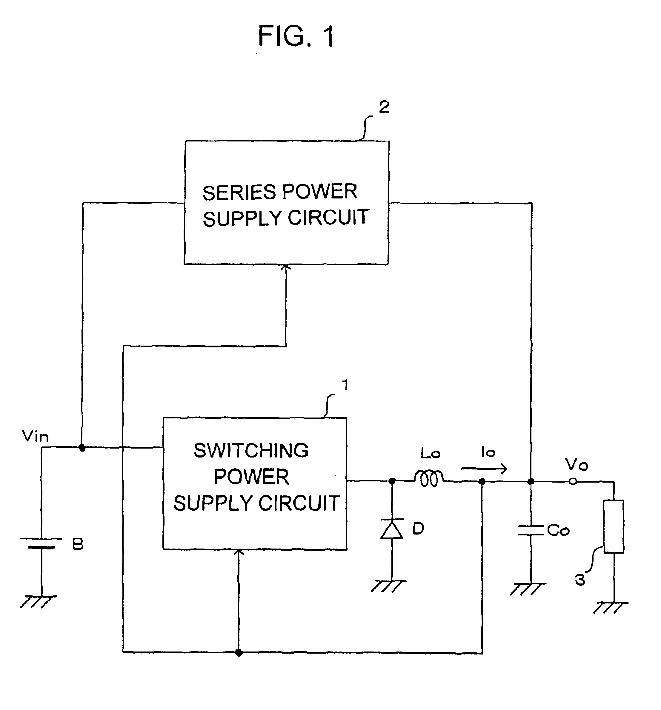
[0030]FIG. 3 is a general circuit arrangement of an electric power supply unit according to the invention. FIGS. 4 and 5 illustrate operations of the power supply unit.

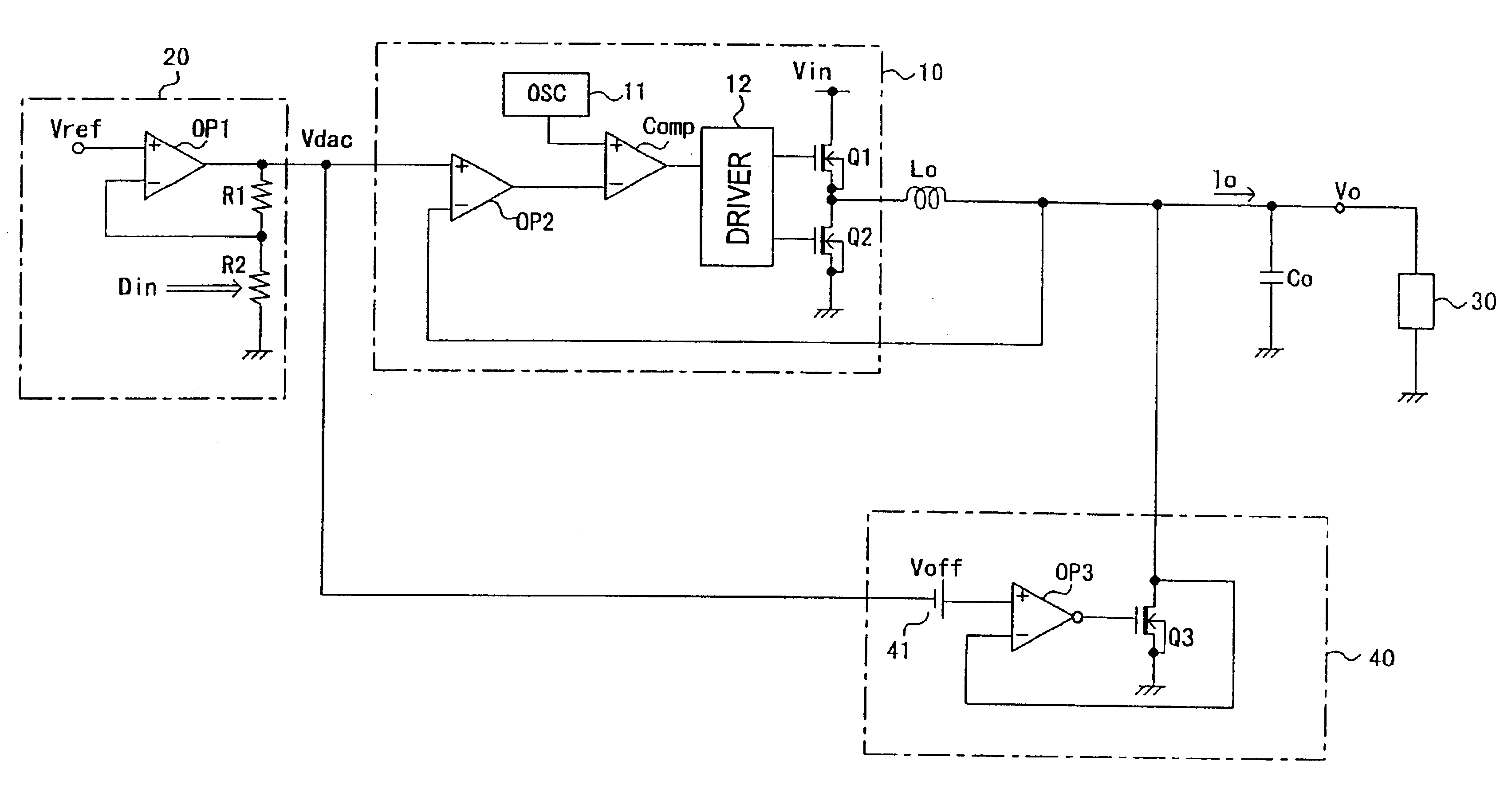
[0031]As shown in FIG. 3, there is provided a switching DC / DC power supply circuit section 10 having a switching circuit which includes n-type MOS transistors (hereinafter referred to as n-type transistors) Q1 and Q2 connected in series between a source voltage Vin and the ground. The switching DC / DC power supply circuit section 10 also includes an error amplifier OP2, an oscillator 11, a comparator Comp, and a driver 12. The error amplifier OP2 has a non-inverting input terminal (+) for receiving an instruction voltage Vdac and an inverting terminal (−) for receiving the output voltage Vo of the power supply unit or a feedback voltage associated with the output voltage Vo. The error amplifier OP2 provides at its output terminal an amplified difference between the two input voltages.

[0032]The oscillator 11 generates a...

second embodiment

[0049]Next, referring to FIG. 6, there is shown an arrangement of an operational amplifier OP3 that allows for a variable slewing rate in accordance with the invention. Slewing rate is defined to be a magnitude of rise or fall in the output per unit time for a given step-up or step-down change in the input. FIG. 7 shows a circuit diagram of a mutual conductance amplifier for use as the operational amplifier shown in FIG. 6. FIG. 8 is a graphical representation of the operations of the power supply unit utilizing the operational amplifier shown in FIG. 6.

[0050]As shown in FIG. 6, the operational amplifier OP3 has a difference amplifier 42 and a GM amplifier 44. The difference amplifier 42 is supplied with a summed voltage (Vdac+Voff) and the output voltage Vo, and amplifies the difference voltage between them.

[0051]The difference amplifier of FIG. 6 includes a first series branch consisting of a resistor R3 and an npn-type bipolar transistor (hereinafter referred to as npn transistor...


PUM


Abstract

The power supply unit is provided with a power supply circuit adapted to generate an output voltage in accord with an instruction voltage, an output condenser Co connected to the output end of the power supply circuit, and an auxiliary output voltage setting circuit adapted to compare the instruction voltage and the output voltage and to cause the output condenser to discharge its electric charge when the instruction voltage becomes lower than the output voltage. Because of the auxiliary output voltage setting circuit, the power supply circuit quickly generates an output voltage in accord with the instruction voltage if the instruction voltage is lowered.

Description

FIELD OF THE INVENTION[0001]This invention relates to an electric power supply unit having improved output voltage response to a change in instruction voltage.BACKGROUND OF THE INVENTION[0002]Switching power supply units have been widely used as power supply units for efficiently converting a given supply voltage to a lower voltage. In order to smooth the intermittent output voltage arising from switching, a switching power supply unit has at the output end thereof a smoothing coil and an output condenser.[0003]The smoothing coil and the output condenser will delay the output voltage if a load is suddenly changed. Thus, there has been proposed an improved power supply unit adapted to alleviate the delay in the response to a change in load, as disclosed in, for example, Japanese Patent Early Publication H10-98874.[0004]FIG. 1 shows a general circuit arrangement of a power supply unit having an improvement in response to a delay pertinent to conventional circuits. A switching power su...

Claims


Application Information

Patent Timeline
Patent Type & Authority Patents(United States)
IPC IPC(8): H02M3/04H02M3/158H02J1/00H02M3/155
CPCH02M3/1584H02M2001/322H02M2001/0045H02M1/0045H02M1/322
Inventor TAKEMURA, KOUMEMOTO, KIYOTAKANAKATA, KENICHI
Owner ROHM CO LTD
Why Eureka
Try Eureka