Method and device for operating a drive train of a hybrid vehicle

a hybrid vehicle and drive train technology, applied in the field of hybrid vehicles, can solve the problems of increased torque, voltage dip, and increase in the rotational speed of the drive train and the electric machine, and achieve the effects of avoiding overloading of the on-board electrical system, avoiding energy-intensive operation, and avoiding high freewheeling rotational speed

Inactive Publication Date: 2013-12-26
ROBERT BOSCH GMBH
View PDF3 Cites 3 Cited by
  • Summary
  • Abstract
  • Description
  • Claims
  • Application Information

AI Technical Summary

Benefits of technology

The invention describes a system for stabilizing the voltage of an on-board electrical system of a vehicle, using two electric machines. The first electric machine is operated in a compensation mode to ensure that the voltage of the electrical system is always within acceptable limits. The normal operating mode load resistance value of the first electric machine is predefined to minimize energy consumption and stabilize the voltage based on the expected load requirements. The second electric machine is used to stabilize changes in voltage that occur at a slower pace. Overall, the system ensures that the voltage of the on-board electrical system is always stable and optimal for the vehicle's performance.

Problems solved by technology

When high-power loads, for example an electrically operated vehicle air-conditioning system, are switched on, on the one hand electrical power peaks are produced, and therefore voltage dips in the on-board electrical system of the vehicle, and on the other hand the rotational speed of the drive train and of the electric machine which is operated in a generator mode collapses since the internal combustion engine does not output within a very short time a significantly increased torque which is necessary for this purpose.

Method used


Image

  • Method and device for operating a drive train of a hybrid vehicle
  • Method and device for operating a drive train of a hybrid vehicle
  • Method and device for operating a drive train of a hybrid vehicle

Examples


Embodiment Construction

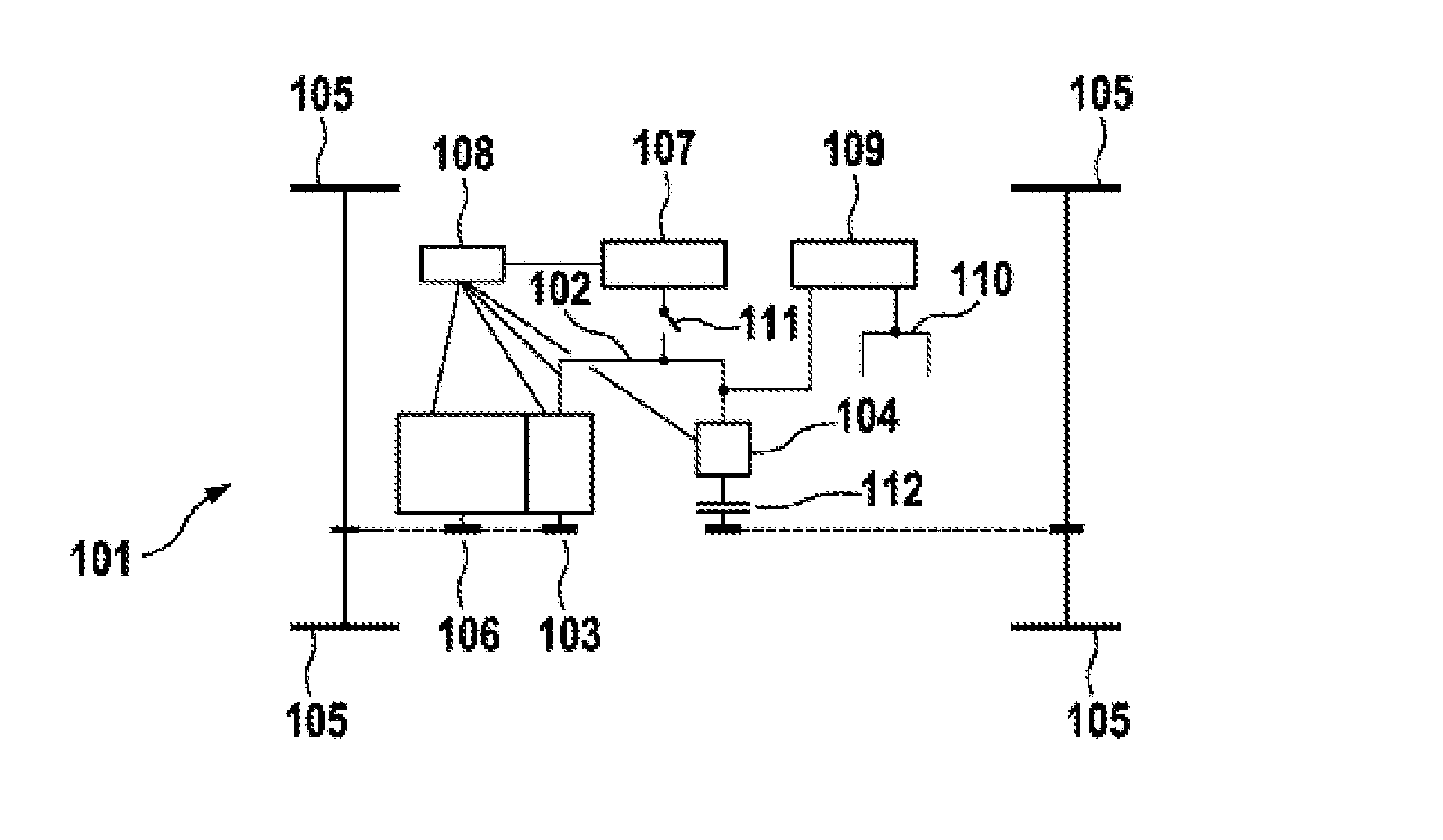
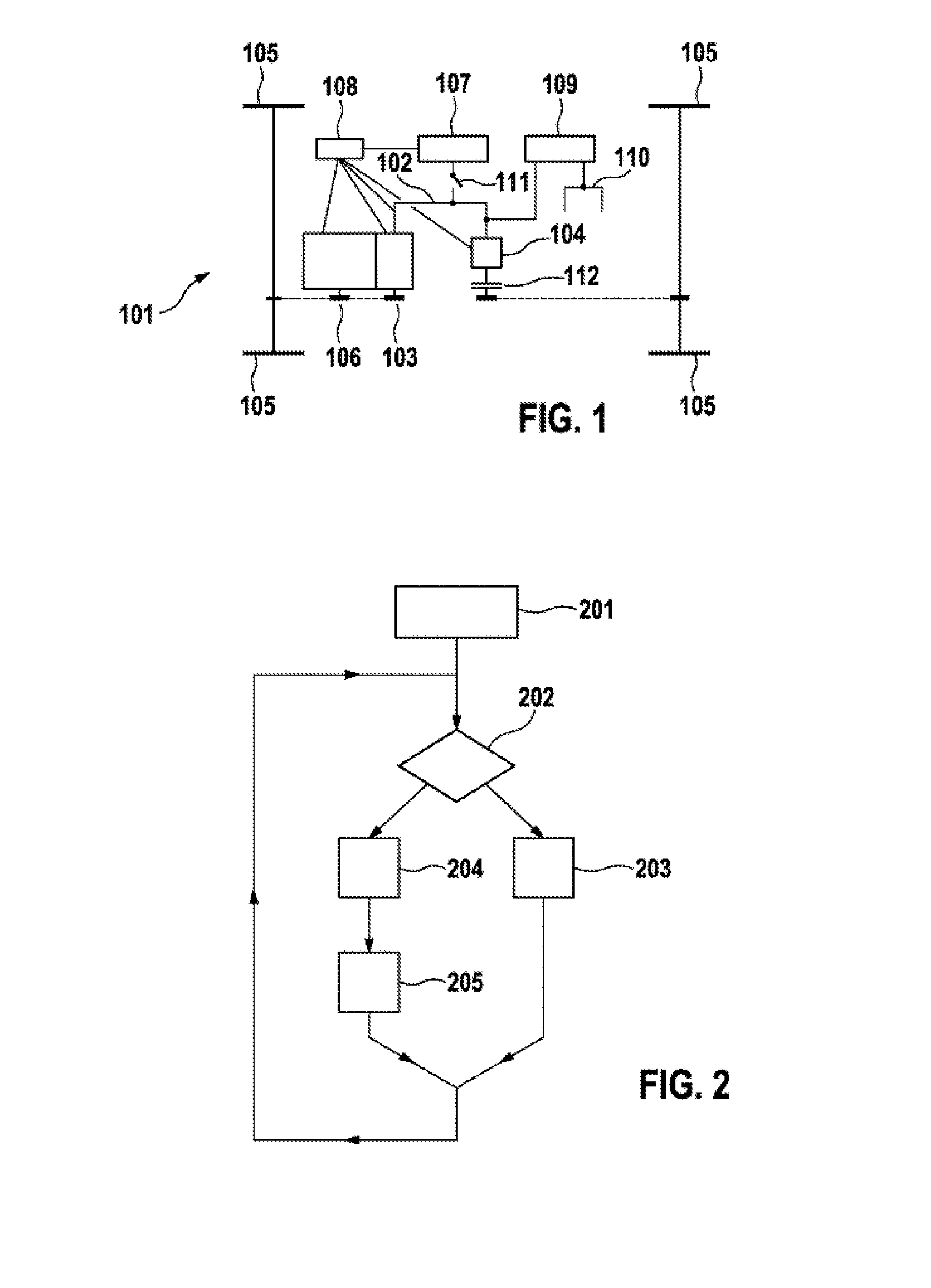
[0027]FIG. 1 shows a basic illustration of a vehicle drive train 101 of a vehicle comprising a hybrid drive. The second electric machine 103 and the first electric machine 104 as well as a DC / DC converter 109 are connected to the on-board electrical system 102. The connection of a low-voltage on-board electrical system 110, to which further loads (not illustrated) which can be activated and deactivated are connected, is indicated on the DC / DC converter 109. Furthermore, a high-voltage battery 107 as well as means, for example a control unit 108, for actuating the components (102, 103, 104, 106, 107), are connected to the high-voltage on-board electrical system. The control unit 108 could also be connected to the low-voltage on-board electrical system 110 depending on the electrical embodiment. The second electric machine 103 can be mechanically coupled to the internal combustion engine 106 so that the latter can drive the second electric machine 103. In this context, the second elec...


PUM


Abstract

The invention relates to a method and a device for operating a drive train (101) of a hybrid vehicle comprising an electrical system (102), the drive train (101) having at least one vehicle drive wheel (105) in addition to one first electrical machine (104) and the first electrical machine (104) being connected to the electrical system (102). According to the invention, in order to stabilise the voltage of the electrical system (102), the first electrical machine (104) is operated without being coupled to the drive wheels (105) of the hybrid vehicle.

Description

BACKGROUND OF THE INVENTION[0001]The invention relates to a hybrid vehicle comprising a drive train which has two electric machines, wherein both serve to drive the vehicle on one drive axle each, which drive axles are not mechanically coupled to one another, is known as the vehicle RX450h from Lexus. The electrical loads of the vehicle are connected to energy sources via an on-board electrical system. Vehicles with an electric traction drive have a high-voltage on-board electrical system for supplying the electric drive and further high-voltage loads. The high-voltage on-board electrical system is connected to a low-voltage on-board electrical system which serves to supply the low-voltage loads of the vehicle.[0002]It is known to operate one of the electric machines of a hybrid vehicle at certain times in a generator mode in order to generate electrical energy to supply the loads and to charge the energy accumulators. When high-power loads, for example an electrically operated vehi...

Claims


Application Information

Patent Timeline
Patent Type & Authority Applications(United States)
IPC IPC(8): B60L11/16B60L50/15B60L50/16B60L50/30
CPCB60L11/16B60K6/387B60K6/46B60K6/52B60W10/02B60W20/00B60W2710/248B60Y2400/3086H02J3/18Y02E40/30B60L1/003B60L15/20B60L3/0046B60L2210/40B60L2240/34B60L2240/421B60L2240/423B60L2240/547B60L2260/28B60L50/61B60L50/16B60L50/30Y02T10/62Y02T10/64Y02T10/72Y02T10/7072Y02T10/70B60W10/08B60W20/13
Inventor FANKHAUSER, PHILIPSTAVRIANOS, DIMITRIOSWALD, KLAUS-JUERGENRAICHLE, DANIELHEIDRICH, TORSTENWIRTH, MARTIN
Owner ROBERT BOSCH GMBH
Why Eureka
Try Eureka