DC brush motor and permanent magnet used therein

a brush motor and permanent magnet technology, applied in the direction of magnetic circuits, magnetic bodies, magnetic circuits characterised by magnetic materials, etc., can solve the problems of inability to realize high-output motors, inability to miniaturize such small-sized motors, and inability to achieve high-output motors. , to achieve the effect of improving the mechanical properties, reducing the volume of the motor, and reducing the size and weigh

Inactive Publication Date: 2005-07-12
AICHI STEEL
View PDF24 Cites 14 Cited by
  • Summary
  • Abstract
  • Description
  • Claims
  • Application Information

AI Technical Summary

Benefits of technology

[0009]The purpose of the present invention is to solve the aforementioned problems that have long plagued the small-sized brush motor industry by either reducing the volume of the motor by ½ while maintaining the same properties of the conventional motor, thus greatly reducing size and weight, or by improving the motor properties twofold while reducing the volume by 20% compared to the conventional motor, thus greatly improving the properties.
[0010]In other words, a motor with high properties, such as twice the performance index T of the technological benchmark of the conventional motor using sintered ferrite, can be offered.
[0011]At the same time, by minimization of uneven torque, the quietness can be improved, and the process of gluing several magnets can be omitted from the manufacturing process.

Problems solved by technology

In recent years, there has been a demand for the miniaturization of such small-sized motors, however this has not been realized because sintered ferrite magnets with thin enough wall thickness cannot be manufactured due to the shrinkage of sintered ferrite magnets during sintering.
Moreover, high-output motors could not be realized as sintered ferrite magnets have a low attractive force.
In addition, if one attempts to make a large-size motor in order to achieve high output, there is no alternative but to make a 4-pole motor, as the arc length is too great for a 2-pole motor.
In this case of a 4-pole motor using sintered ferrite magnets, the size and weight are increased, and it is not possible to improve the motor performance index (torque constant / volume).
Furthermore, as the shape of sintered ferrite magnets differs depending on the environmental conditions, such as humidity and the sintering conditions, it is difficult to achieve tiled sintered ferrite magnets of exactly the same dimensions.
Because of this, the problem of squeaking and rattling can occur due to uneven torque resulting from errors in symmetry of the magnetic field made during precision arrangement.
However, these magnets were not adopted because when motor manufacturers simply tried to replace the ferrite magnets of conventional small-sized brush motors with these magnets having four times the maximum energy product, the motor properties only increased on the order of 20%, and because the back yoke needed to be doubled, the size actually increased.
In addition, as the motor properties depend on several factors such as armature shape and properties, back yoke thickness and material, coils, etc., the increase in properties could only be expected to be on the order of 20% and therefore these magnets have not been adopted in recent years.

Method used


Image

  • DC brush motor and permanent magnet used therein
  • DC brush motor and permanent magnet used therein
  • DC brush motor and permanent magnet used therein

Examples


embodiment 1

(Embodiment 1)

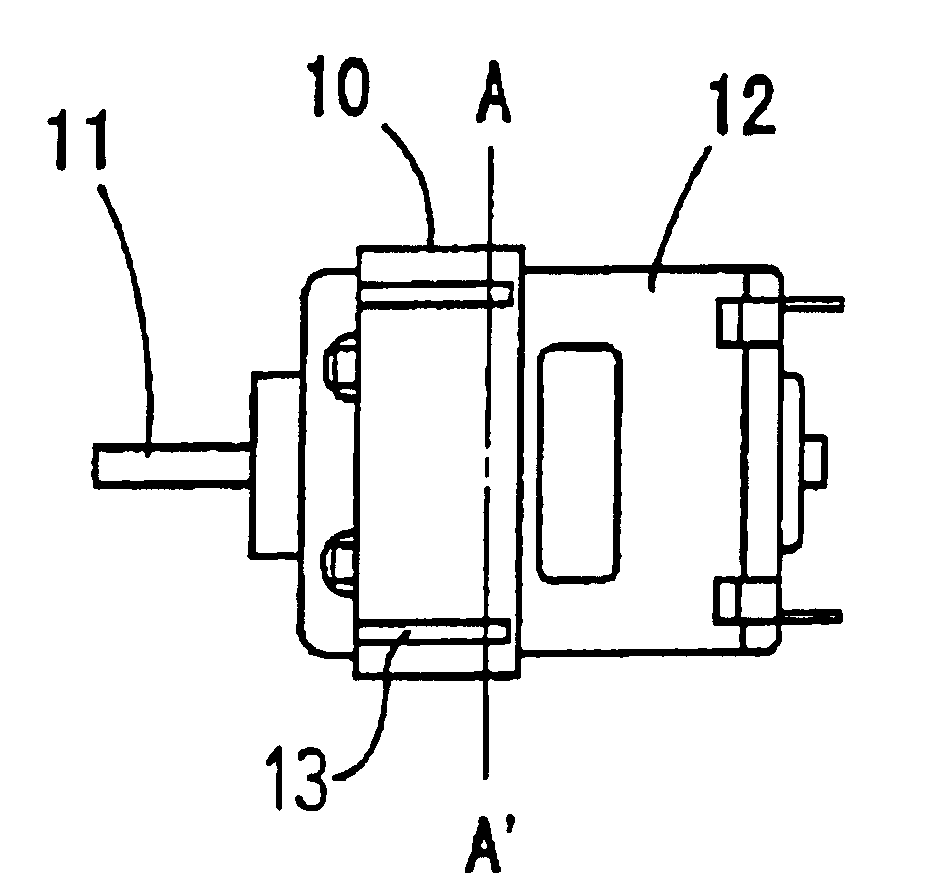
[0061]FIGS. 1A and 1B shows an example motor of the present embodiment. This figure includes the side view 1A and the cross sectional view 1B through AA′. The purpose of the present embodiment is to make a smaller motor than the conventional motor. The motor of the present embodiment is comprised of a housing 12, an anisotropic rare earth bonded magnet 13 as the hollow cylinder permanent magnet set in the inner perimeter of the housing 12, an armature 14 making the electromagnetic rotor core set in the center, coils 15 wrapped around armature 14, a rotary shaft 11 extending from the center of armature 14, and a back yoke 10 that is a flux ring for prevention of magnetic flux leakage. The back yoke is a part of the housing. The motor housing and the back yoke have the same function as a magnetic circuit. Therefore In the present embodiment, the housing outer diameter as mentioned in the claims is the diameter of the back yoke. For a volume comparison, the conventional 2...

embodiment 2

(Embodiment 2)

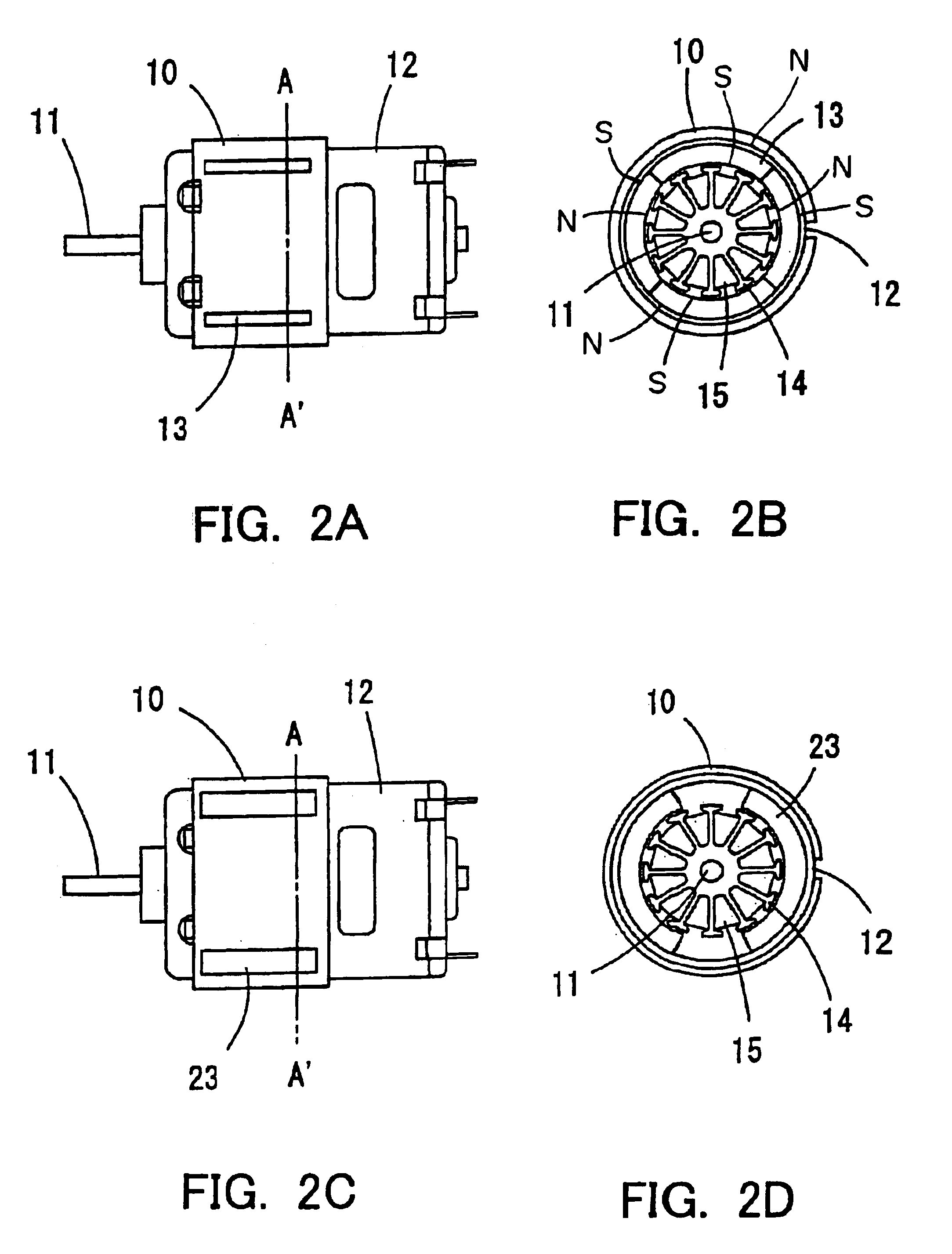
[0078]Embodiment 1 was an example of the size reduction of the conventional motor by the use of an anisotropic rare earth bonded magnet. Using this anisotropic rare earth bonded magnet, with adjustment of radial thickness, it is possible to increase the motor torque. The present embodiment is an example of using an anisotropic rare earth bonded magnet to double the torque.

[0079]For example, the conventional motor using sintered ferrite magnet 23 has a torque of 75.7 (mN*m / A), a volume of approximately 56.1 cm3, which is to say a motor performance index T of T=1.35, and all other dimensions the same as those of the conventional motor explained in embodiment 1.

[0080]The motor of the present embodiment is shown in FIG. 2. In the present embodiment, the ratio of electromagnetic rotor core radius to housing outer diameter a / r is not less than 0.25 and not greater than 0.5, the ratio of housing thickness to magnet thickness w / d is not less than 1 and not greater than 4, and ...

embodiment 3

(Embodiment 3)

[0082]The motor of embodiment 1, which is a low output level DC brush motor of the present invention, is maintained with the following common-sense conditions (1) the ratio of electromagnetic rotor core radius to housing outer diameter a / r is not less than 0.25 and not greater than 0.5, and (2) the ratio of housing thickness to magnet thickness w / d is not less than 1 and not greater than 4, while the ratio of anisotropic rare earth bonded magnet 13 thickness to housing outer diameter d / r=R (hereafter referred to simply as ratio R) is changed and the motor performance index T is evaluated. The characteristics when anisotropic rare earth bonded magnet 13 has a maximum energy product of 14 MGOe are shown in FIG. 4. When ratio R is in the range not less than 0.01 and not greater than 0.10, the performance index T is greater than twice the performance index T of the conventional 2-pole ferrite motor (1.3). If the ratio R is less than the lower limit of 0.01, even with magne...


PUM

PropertyMeasurementUnit
volumeaaaaaaaaaa
inner diameteraaaaaaaaaa

Abstract

The challenge to be solved by the present invention is the miniaturization of a 1-300 W class of motor. This can be achieved by using a hollow-cylinder shaped anisotropic bonded magnet magnetized in a 4-pole configuration. The anisotropic bonded magnet has a maximum energy product approximately 4 times greater than the conventional sintered ferrite magnets. The use of a 4-pole configuration shortens the magnetic path length of the individual magnetic circuits and the magnetic force contributing to the torque is increased. When the torque is kept the same as in the conventional motor, the length of the electromagnetic rotor core and the axial magnet length can be reduced. In this fashion, 1-300 W class motors can be reduced in size.

Description

[0001]This is a patent application based on Japanese patent applications No. 2002-276194 and No. 2001-375159 which were filed on Sep. 20, 2002 and Dec. 10, 2001, respectively, and which are incorporated herein by reference.BACKGROUND OF THE INVENTION[0002]1. Field of the Invention[0003]The present invention is related to a DC brush motor and a permanent magnet used within. In particular, the present invention is related to a DC brush motor and associated permanent magnet whose small size and high torque are made possible by the use of an anisotropic rare earth bonded magnet as the permanent magnet. The present invention is very effective for example in 1-300 W high-performance small-size DC brush motor applications.[0004]2. Background Art[0005]Prior to 1960, small-sized motors did not use magnets, but were induction brush motors. From 1960, with the appearance of affordable ferrite magnets with a maximum energy product (BHmax) on the order of 4 MGOe, small-sized brushless motors wit...

Claims


Application Information

Patent Timeline
Patent Type & Authority Patents(United States)
IPC IPC(8): H01F7/02H02K1/12H02K1/17H02K23/02H02K23/04H02K1/00H02K1/02H02K15/03
CPCH01F7/021H02K1/17H02K23/04H02K1/02
Inventor HONKURA, YOSHINOBUHASHIMOTO, YOJIMITARAI, HIRONARI
Owner AICHI STEEL
Why Eureka
Try Eureka