
Polycrystalline diamond with improved abrasion resistance

a polycrystalline diamond and abrasion resistance technology, applied in the field of cutting elements, can solve the problems of shortening the operating life reducing the toughness of the cutting element, and reducing the abrasion resistance of the cutting elemen

Inactive Publication Date: 2005-07-12
SMITH INT INC
View PDF8 Cites 35 Cited by
  • Summary
  • Abstract
  • Description
  • Claims
  • Application Information

AI Technical Summary

Benefits of technology

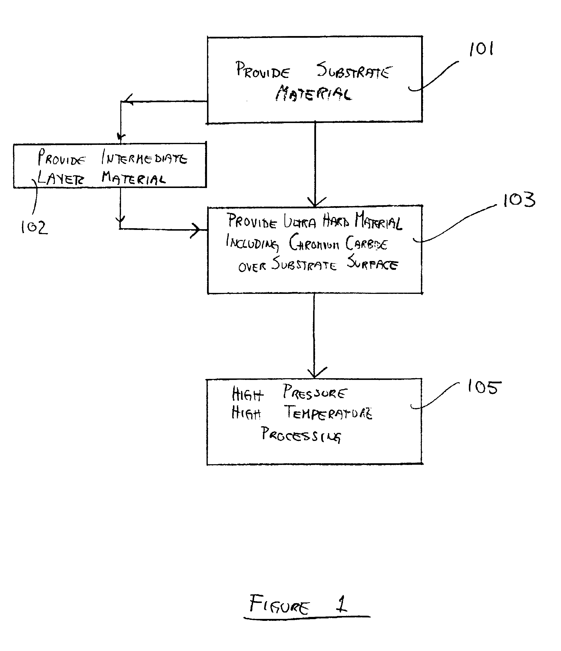
[0009]In another embodiment of the invention, a method for manufacturing a cutting element is provided. The method includes providing a substrate and providing a layer of material including ultra hard particles and chromium carbide, over the substrate. The substrate and layer of material are processed at a sufficiently high temperature and at a sufficiently high pressure to convert the layer of material to a polycrystalline material and to bond the polycrystalline material to the substrate. The polycrystalline material may be polycrystalline diamond or polycrystalline cubic boron nitride. In another exemplary embodiment, the p

Problems solved by technology

Common problems that plague cutting elements having an ultra-hard material layer such as PCD or PCBN bonded to the carbide substrate, are chipping, spalling, partial fracturing, cracking or exfoliation of the cutting table.
These problems result in the early failure of the ultra-hard layer and thus, in a shorter operating life for the cutting element.
Typically, these problems may be the result of peak (high magnitude) stresses generated on the ultra-hard layer at the region in which the layer makes contact with an external surface, such as when the cutting layer makes contact with earthen formations during drilling.
Toughness is sacrificed, however, as finer-grained PCD materials are less robust and more prone to chipping than coarser grades.
Another common problem that plagues cutting elements having an ultra hard material layer bonded to a carbide substrate is the formation of extremely large, undesirable carbide grains along the interface formed between the carbide substrate and the ultra hard material layer.
The presence of such WC particles may cause stress fractures and the early delamination of the ultra hard material layer from the substrate.

Method used


Image

  • Polycrystalline diamond with improved abrasion resistance
  • Polycrystalline diamond with improved abrasion resistance
  • Polycrystalline diamond with improved abrasion resistance

Examples


Embodiment Construction

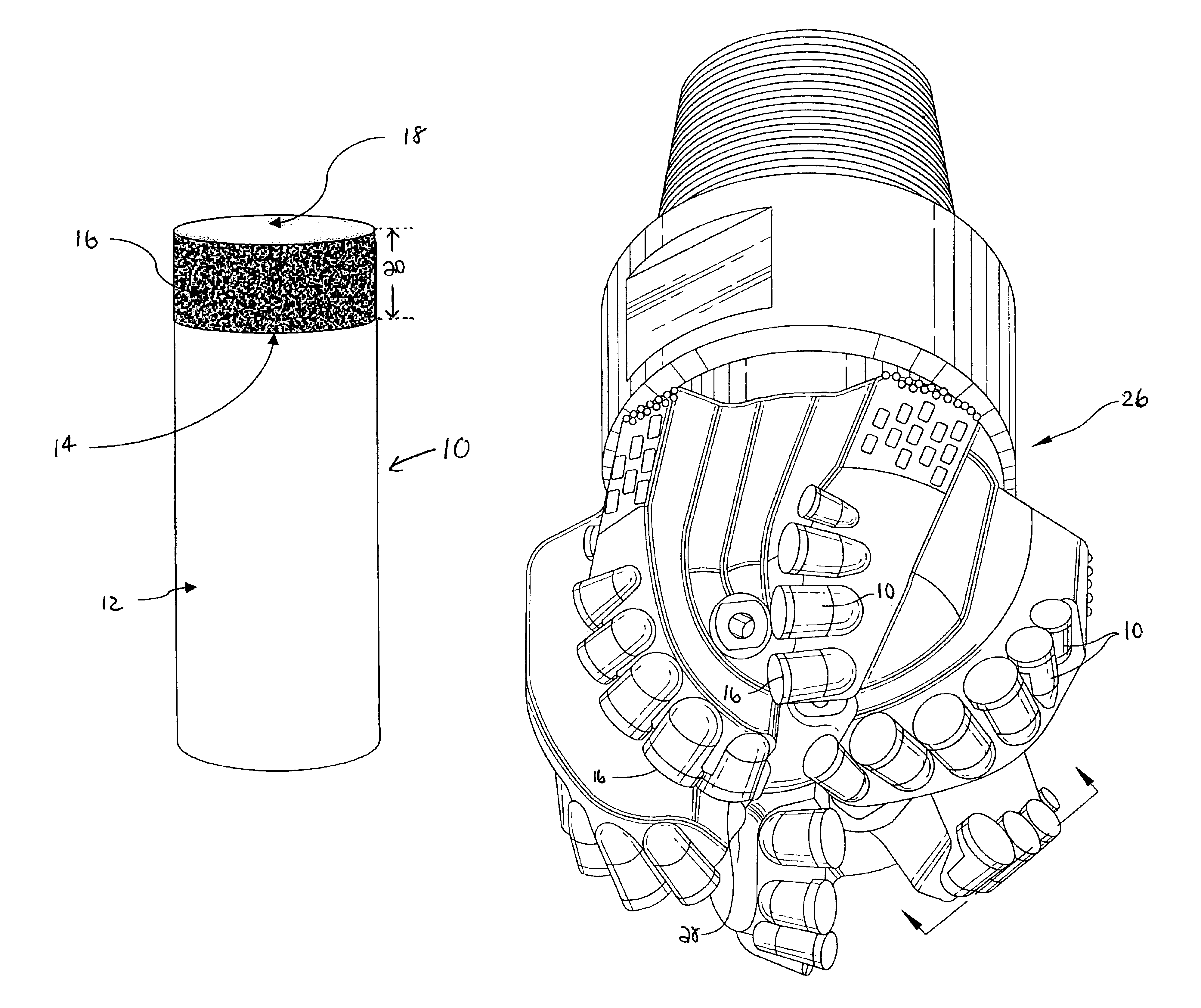
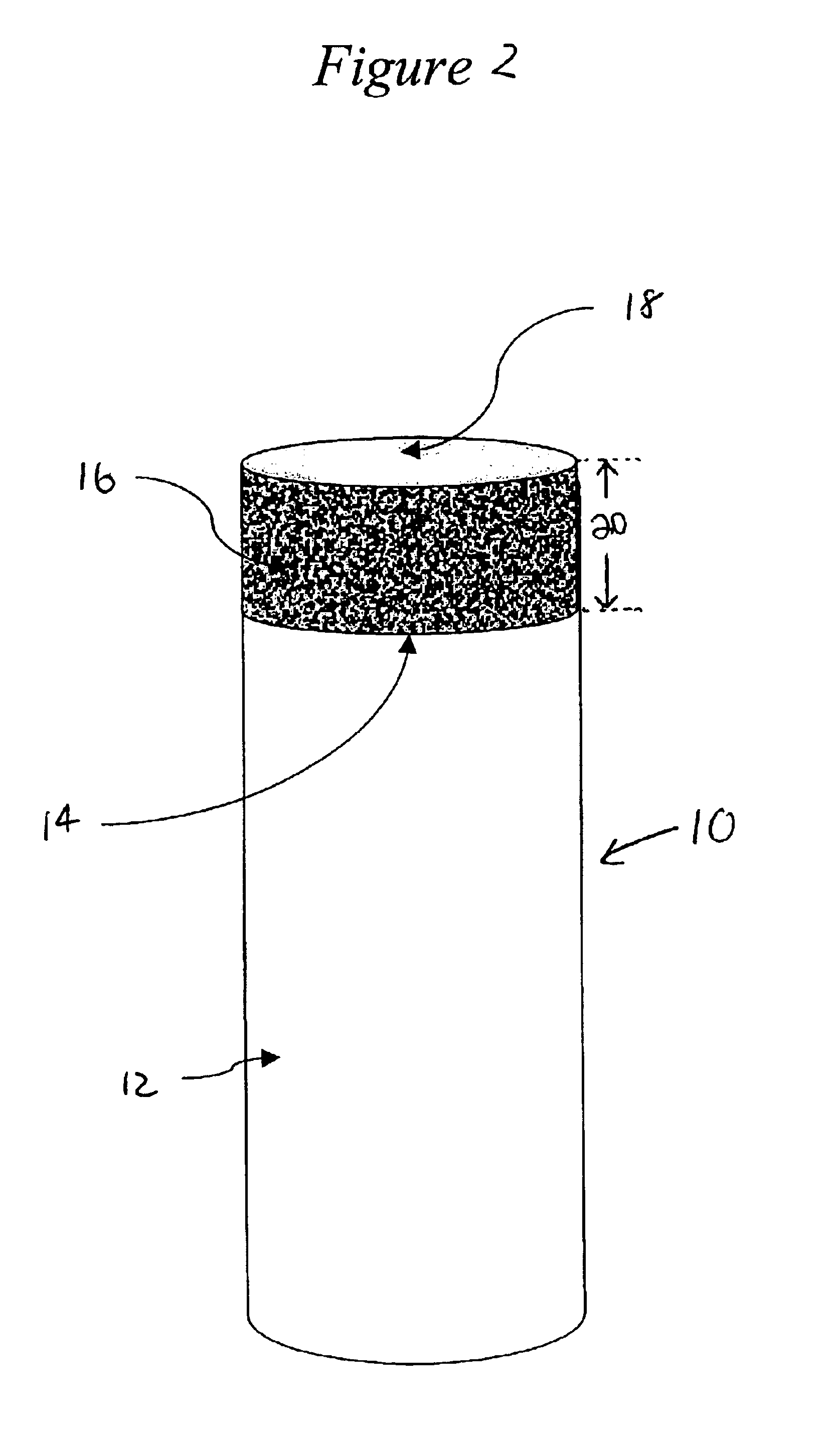
[0020]The present invention provides an ultra hard polycrystalline layer that exhibits improved abrasion resistance without sacrificing toughness. In one illustrative embodiment, the present invention finds application in cutting elements and earth boring bits incorporating cutting elements used for removing earth. The present invention also finds application in other cutting elements and other tooling elements in which an ultra hard layer is advantageously utilized. More particularly, the present invention is directed to an ultra hard cutting layer metallurgically bonded to a substrate, the ultra hard cutting layer formed of a polycrystalline material and including chromium carbide and / or chromium and carbon. The polycrystalline material may be PCD or PCBN, for example. The present invention is also directed to a bit body incorporating the cutting elements. The present invention is further directed to a method for manufacturing a cutting element including the ultra hard cutting lay...


PUM

PropertyMeasurementUnit
Fractionaaaaaaaaaa
Grain sizeaaaaaaaaaa
Ratioaaaaaaaaaa

Abstract

A cutting element and bit incorporating the cutting element is provided, as well as a method for forming the same. The cutting element includes an ultra hard material layer including chromium and carbon and exhibiting increased abrasion resistance without sacrificing toughness. The method for manufacturing the cutting element includes providing a layer of ultra hard material particles and chromium carbide over the substrate, and then sintering to form the cutting element.

Description

FIELD OF THE INVENTION[0001]The present invention is related most generally to cutting elements, and a method for forming the same. More particularly, the invention is directed to a cutting element having an ultra hard polycrystalline cutting layer formed using chromium carbide.BACKGROUND OF THE INVENTION[0002]Cutting elements such as shear cutters for rock bits, for example, typically have a body (or substrate), which has a contact face. An ultra hard layer is bonded to the contact face of the body by a sintering process to form a cutting layer sometimes referred to as a “cutting table”. The body is generally made from tungsten carbide-cobalt (sometimes referred to simply as “tungsten carbide” or “carbide”), while the ultra-hard layer is a polycrystalline ultra hard material layer, such as polycrystalline diamond (“PCD”) or polycrystalline cubic boron nitride (“PCBN”). There is typically a matrix of binder material within the polycrystalline material.[0003]Common problems that plag...

Claims


Application Information

Patent Timeline
IPC IPC(8): E21B10/46E21B10/56C04B35/5831E21B10/567
CPCC04B35/52C04B35/5831E21B10/567C04B2235/3839C04B2235/405C04B2235/427C04B2235/5436C04B2235/725C04B2235/96C22C26/00E21B10/46E21B10/56
Inventor MIDDLEMISS, STEWART
Owner SMITH INT INC
Learn More