
Auto-balancing apparatus having balancer clamping mechanism for optical disk drives

a technology of optical disk drives and clamping mechanisms, which is applied in the direction of magnetic recording, data recording, instruments, etc., can solve the problems of increasing the centrifugal wobbling force caused by unbalanced disk weight, affecting the stability of optical read-write heads, etc., to achieve the effect of limiting the scope of invention

Inactive Publication Date: 2005-07-05
LITE ON IT
View PDF4 Cites 10 Cited by
  • Summary
  • Abstract
  • Description
  • Claims
  • Application Information

AI Technical Summary

Benefits of technology

[0011]In view of the foregoing disadvantages, the primary object of the invention is to provide an auto-balancing apparatus for optical disk drives to expand the conventional auto-balancing apparatus used with read-only storage devices to re-writable storage devices such as CD-ROM, DVD-R / RW and DVD-RAM, and the like. The re-writable storage devices can then read data at high speeds, and also can write data at low operating speeds.
[0012]To achieve the foregoing objects, the auto-balancing apparatus of the invention includes a balance weight, a housing for holding the balance weight, and a clamp mechanism. The clamp mechanism is engaged with the spindle of a spindle motor or the housing through an elastic element.
[0013]The foregoing, as well as additional objects, features and advantages of the invention will be more readily apparent from the following detailed description, which proceeds with reference to the accompanying drawings. The drawings are only to serve for reference and illustrative purposes, and are not intended to limit the scope of the invention.

Problems solved by technology

When the spindle motor operates at high speeds, the centrifugal wobbling force caused by unbalanced weight of the disk also increases.
As a result, greater vibrations and noises will occur.
When the optical disk drives are put to practical use, excessive vibration and noise will make the optical read-write head unstable and make the optical disk drives unable to read data at their maximum rotation speed.
The noise generated while optical disk drives are operating at high speeds also becomes an annoyance to many users.
Hence, to reduce vibration and ensure that optical disk drives are capable of reading data accurately and smoothly at their maximum rotation speed has become a critical issue faced by optical disk drive producers these days.
However for re-writable optical disk drives, operation of the spindle motor for writing data often encounters certain conditions.
At low rotation speeds, the balance weight becomes very unstable and tends to roll easily.
It could lose the effect of offsetting the unbalanced weight.
Moreover, the rolling generates noise or produces interference to the spindle motor, and makes the server system unable to control the motor to rotate at steady speeds.
Hence conventional auto-balancing apparatus are not applicable to re-writable optical disk drives.

Method used


Image

  • Auto-balancing apparatus having balancer clamping mechanism for optical disk drives
  • Auto-balancing apparatus having balancer clamping mechanism for optical disk drives
  • Auto-balancing apparatus having balancer clamping mechanism for optical disk drives

Examples


Embodiment Construction

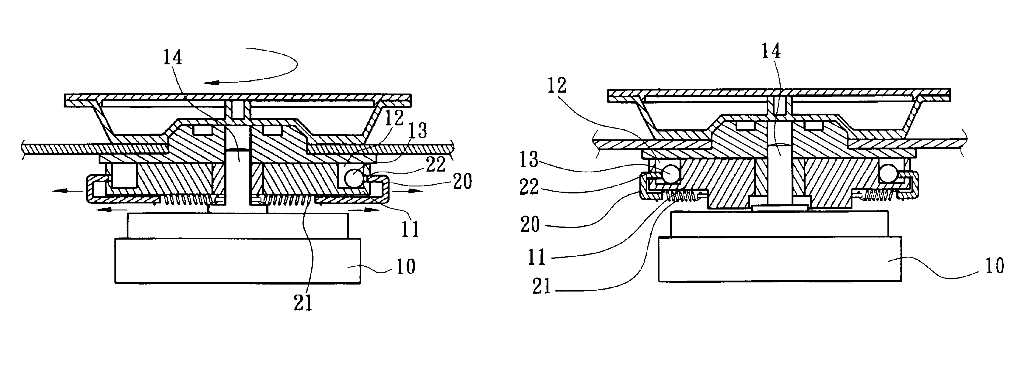
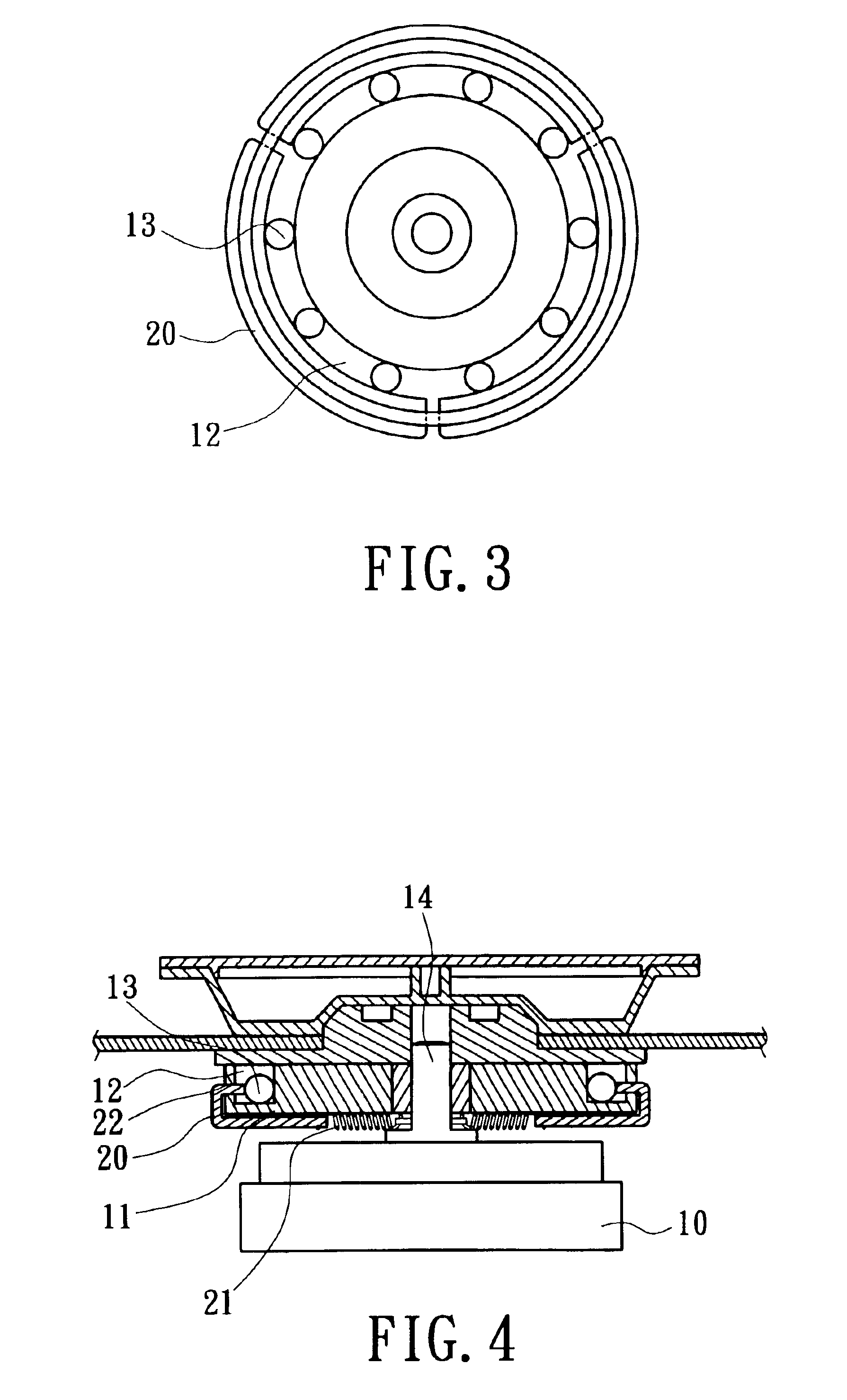
[0021]Referring to FIGS. 3 and 4, the auto-balancing apparatus for optical disk drives of the invention is located above (or below) a spindle motor 10 and includes a housing 11, which may be rotated synchronously with the spindle motor 10. The housing 11 is circular and has a circular orbit 12 around its spindle axis. The orbit 12 is an annular groove and holds thereon at least one balance weight (steel ball) 13.

[0022]In an embodiment of the invention, the perimeter of the housing 11, which holds the balance weight 13, is coupled with a plurality of clamp mechanisms 20 that are movable radially. The clamp mechanisms 20 are respectively engaged with a spindle 14 of the spindle motor 10 or the housing 11 (as shown in FIG. 7) through an elastic element 21 (such as a spring). When the spindle motor 10 is stationary, the clamp mechanisms 20 are pulled by the elastic element 21 through a slot 22 formed on the perimeter of the housing 11 to clamp the balance weight 13. Thus the balance wei...


PUM

PropertyMeasurementUnit
weightaaaaaaaaaa
perimeteraaaaaaaaaa
centrifugal forceaaaaaaaaaa

Abstract

An auto-balancing apparatus for optical disk drives mainly includes a housing for holding a balance weight and a plurality of clamp mechanisms movable radially through the perimeter of the housing. The clamp mechanisms are engaged with a spindle of a spindle motor or the housing through elastic elements. When the spindle motor is not rotating, the balance weight is anchored at a desired position by the clamp mechanisms because of the elastic force of the elastic elements. When operating at high rotation speeds, the engagement force of the elastic elements exerted on the clamp mechanisms is smaller than the centrifugal force, and the balance weight may be moved freely to automatically reach a balanced condition. When operating at low rotation speeds, the server system drives the spindle motor to rotate at speeds faster than the critical rotation speed to reach a balanced condition, then slows down the rotation speed to allow the engagement force exerted on the clamp mechanisms to be greater than the centrifugal force and anchor the balance weight. Thus the auto-balancing apparatus can achieve a balance effect at low rotation speeds.

Description

FIELD OF THE INVENTION[0001]The invention relates to an auto-balancing apparatus for optical disk drives, and particularly a novel auto-balancing apparatus for re-writable storage devices that provides an effective and reliable means of reducing vibration during optical disk drive operation caused by disks of unbalanced weight, to achieve accurate data reading or writing with smooth operation at high speeds.BACKGROUND OF THE INVENTION[0002]Rapid technological innovations and developments in information access and retrieval have greatly improved functionality of optical media in recent years. As a result, reading speed of optical disk drives, which are used as computer peripheral devices, has also made great progress. Nowadays, CD-ROMs with spindle motor rotation speed exceeding 10,000 RPM have become mainstream products on the market.[0003]When the spindle motor operates at high speeds, the centrifugal wobbling force caused by unbalanced weight of the disk also increases. As a resul...

Claims


Application Information

Patent Timeline
Patent Type & Authority Patents(United States)
IPC IPC(8): G11B19/20
CPCG11B19/2009G11B19/2027
Inventor LIAO, CHENG-YAOCHEN, TZU-NAN
Owner LITE ON IT
Learn More