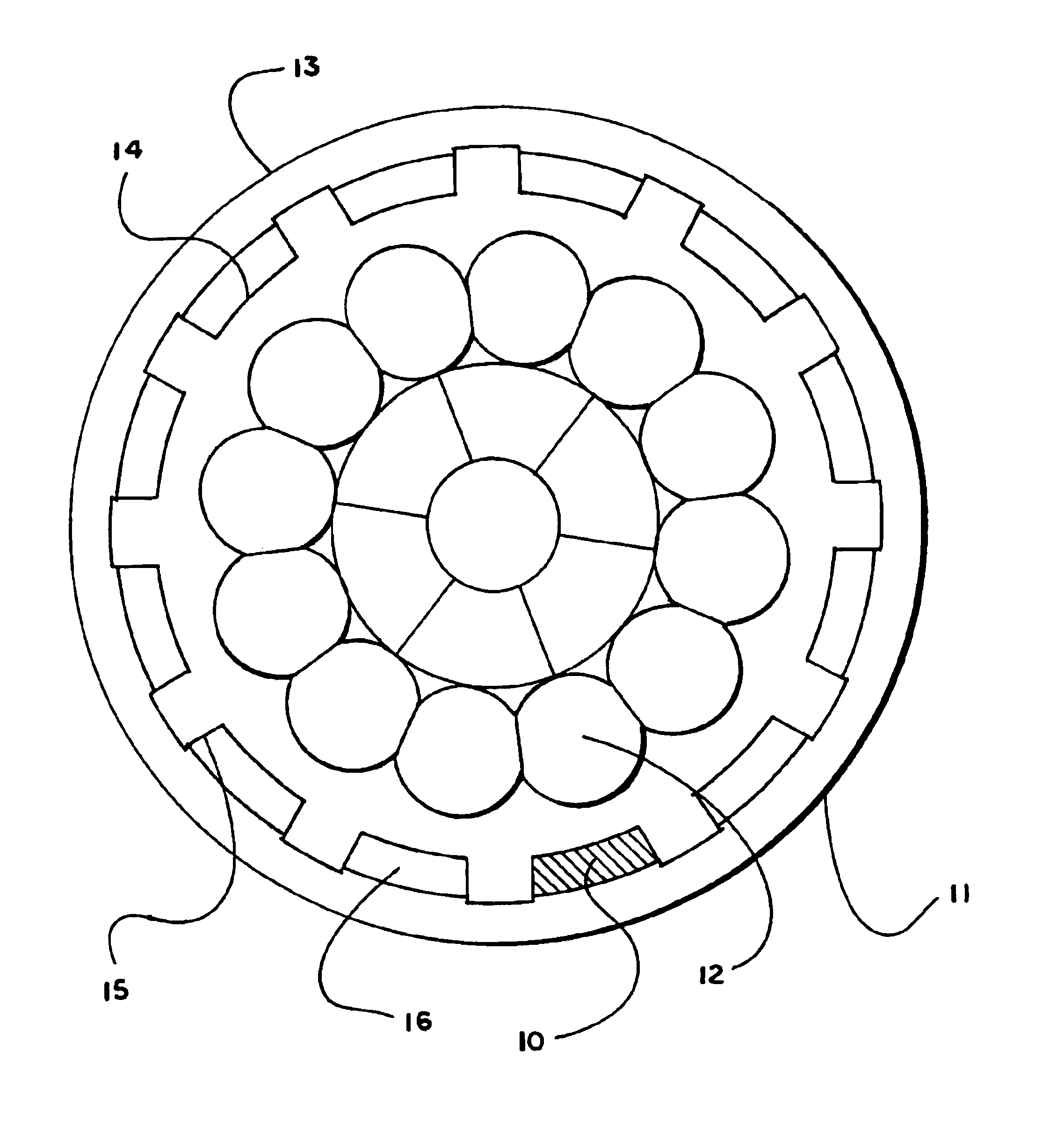
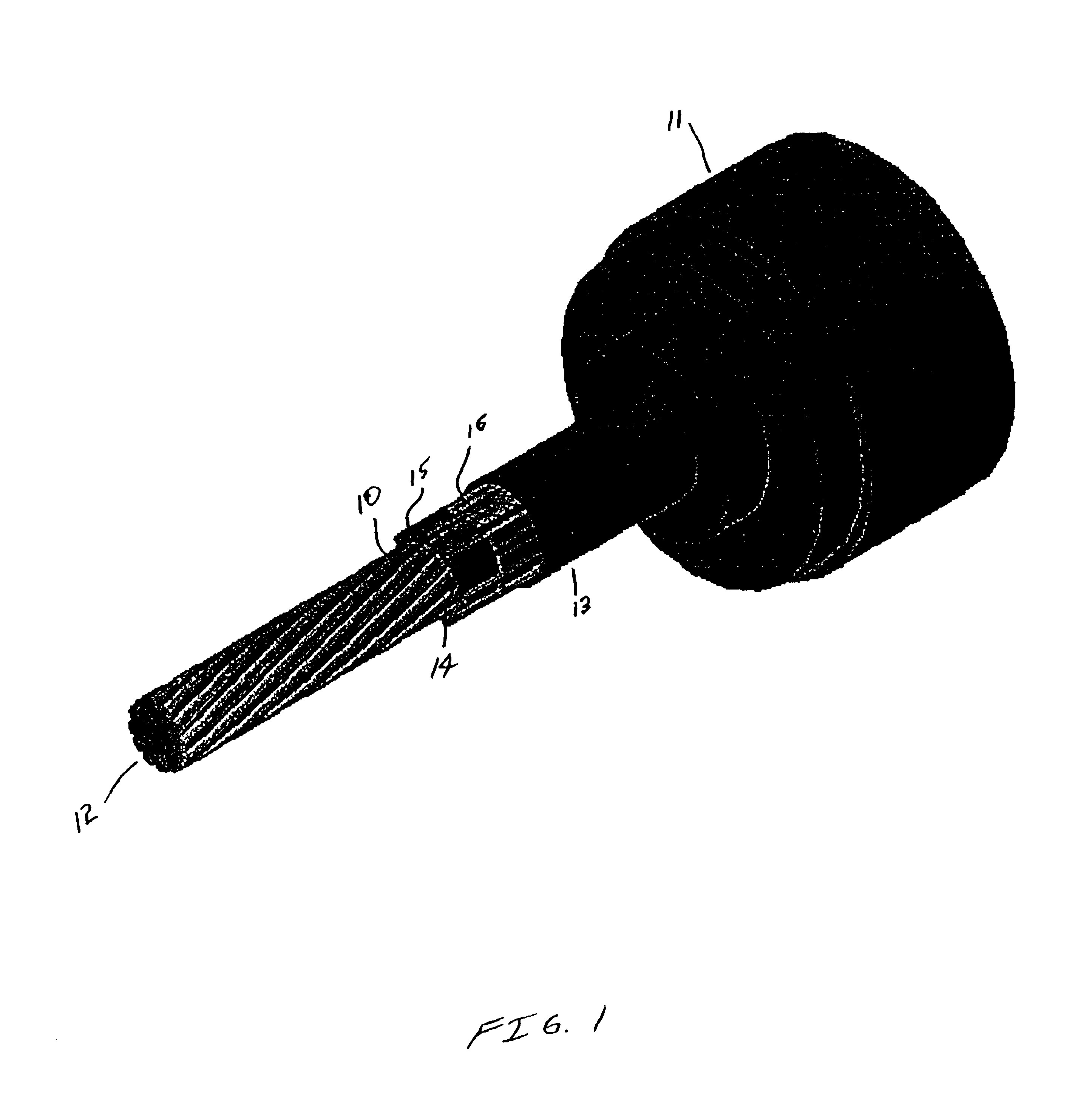
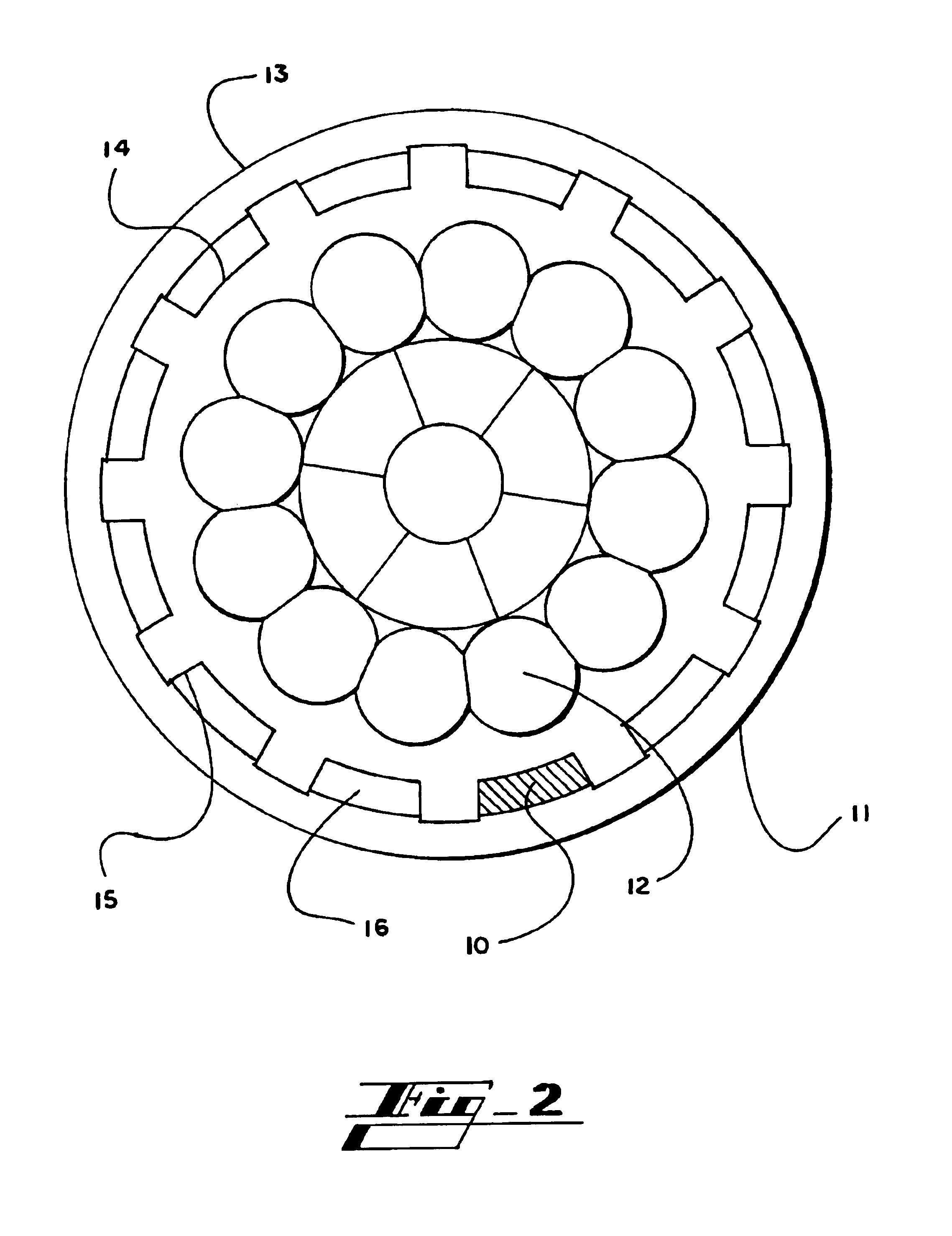
Self-sealing electrical cable having a finned or ribbed structure between protective layers
a technology of protective layer and fin, which is applied in the direction of insulated conductors, cables, conductors, etc., to achieve the effect of avoiding damage to the fins
- Summary
- Abstract
- Description
- Claims
- Application Information
AI Technical Summary
Benefits of technology
Problems solved by technology
Method used
Image

Examples
example 1
[0071]This test was designed to evaluate the performance of the present invention's self sealing, 600 V underground cable. The test program was patterned after a previously developed procedure to evaluate self-sealing or self-repairing cable designs.
[0072]To conduct the test damaged cables were placed in a specially mixed, moist soil. The cables were then energized with 120 V ac to ground. Measurements made included changes in leakage current to earth and cable conductor resistance. The temperature of each cable near the damage point was also monitored.
[0073]Four control sample replicates and eight self-sealing sample replicates were evaluated. All four control samples failed the test relatively early in the test program. All eight self-sealing samples performed well, with no significant increase in conductor resistance and low leakage current values throughout the 60-day test period.
[0074]Conventional and self-sealing 600 volt underground cable with a 2 / 0 AWG combination unilay alu...
example 2
[0105]A cyclic load test was run on the finned cable of the present invention and compared with similar non-finned prior art cables. 50 ft. samples were tested. The samples had a 50° C. conductor temperature, and were cycled on 8 hours a day and off 16 hours, 7 days a week. The cables were terminated with a mechanical connector. No duct seal, mastic tape, electrical tape, or the like was used. The tops of the samples were approx. 11 ft. above the floor. The samples gradually droop to the floor.
[0106]
Sample 1 (Invention)ShrinkbackShrinkbackTotalWeeks of Agingat Topat BottomShrinkback (in)Initial.0000.0000.00001.3035.1510.4545
[0107]
Sample 2 (Invention)ShrinkbackShrinkbackTotalWeeks of Agingat Topat BottomShrinkback (in)Initial.0000.0000.00001.1385.1880.3265
[0108]
Sample 1 Bare (Prior Art)ShrinkbackShrinkbackTotalWeeks of Agingat Topat BottomShrinkback (in)Initial.8450.22201.067014.63751.20105.838525.5390.82206.361035.9350.67356.608546.1110.61506.726055.9065.58506.491566.3725.60206.9745...
PUM
| Property | Measurement | Unit |
|---|---|---|
| depth | aaaaa | aaaaa |
| depth | aaaaa | aaaaa |
| thickness | aaaaa | aaaaa |
Abstract
Description
Claims
Application Information
 - R&D
- Intellectual Property
- Life Sciences
- Materials
- Tech Scout
- Unparalleled Data Quality
- Higher Quality Content
- 60% Fewer Hallucinations
Browse by: Latest US Patents, China's latest patents, Technical Efficacy Thesaurus, Application Domain, Technology Topic, Popular Technical Reports.
© 2025 PatSnap. All rights reserved.Legal|Privacy policy|Modern Slavery Act Transparency Statement|Sitemap|About US| Contact US: help@patsnap.com