
Apparatus for protecting thermocouple circuits in thermoplastic injection moulding equipment

Inactive Publication Date: 2005-07-05
FAST HEAT
View PDF7 Cites 12 Cited by
  • Summary
  • Abstract
  • Description
  • Claims
  • Application Information

AI Technical Summary

Benefits of technology

[0004]In view of the foregoing, the general object of the present invention is to provide an apparatus for protecting thermocouple circuits in an injection molding machine from being damaged by leakage currents from heaters.
[0005]A related object is to provide a means for protecting the thermocouple circuits from leakage currents that is cost effective and can be easily integrated into the injection molding system.
[0006]A further object of the invention is to provide an apparatus for protecting the thermocouple circuits from leakage currents that also provides the function of filtering out AC line noise to enhance the accuracy of the thermocouple temperature readings.

Problems solved by technology

One problem frequently experienced by manufacturers that use injection molding systems is the damages to the thermocouple circuits caused by leakage current from heating elements.
Such leakage current may destroy the thermocouple wire and damage the thermocouple controller.

Method used


Image

  • Apparatus for protecting thermocouple circuits in thermoplastic injection moulding equipment
  • Apparatus for protecting thermocouple circuits in thermoplastic injection moulding equipment
  • Apparatus for protecting thermocouple circuits in thermoplastic injection moulding equipment

Examples


Embodiment Construction

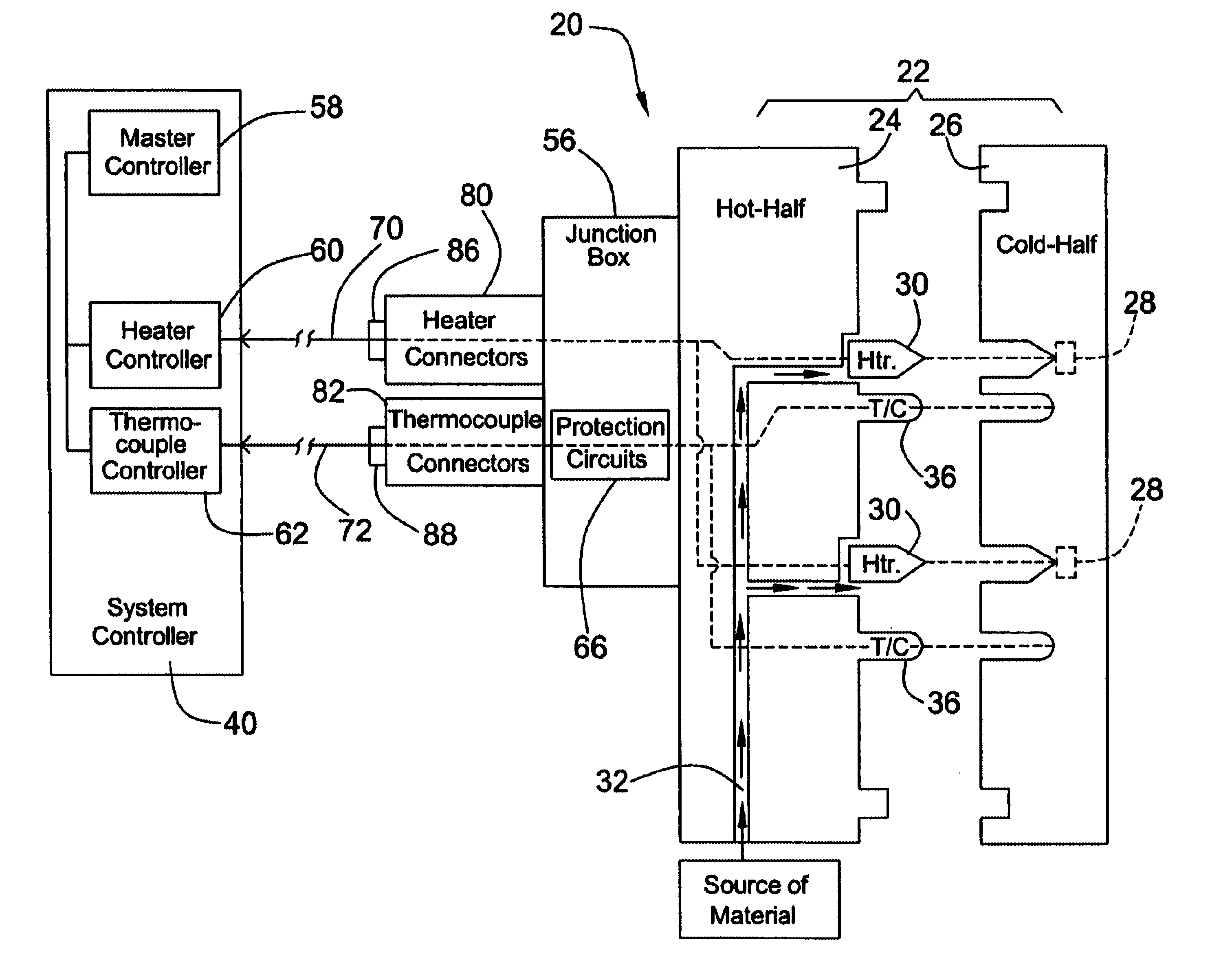
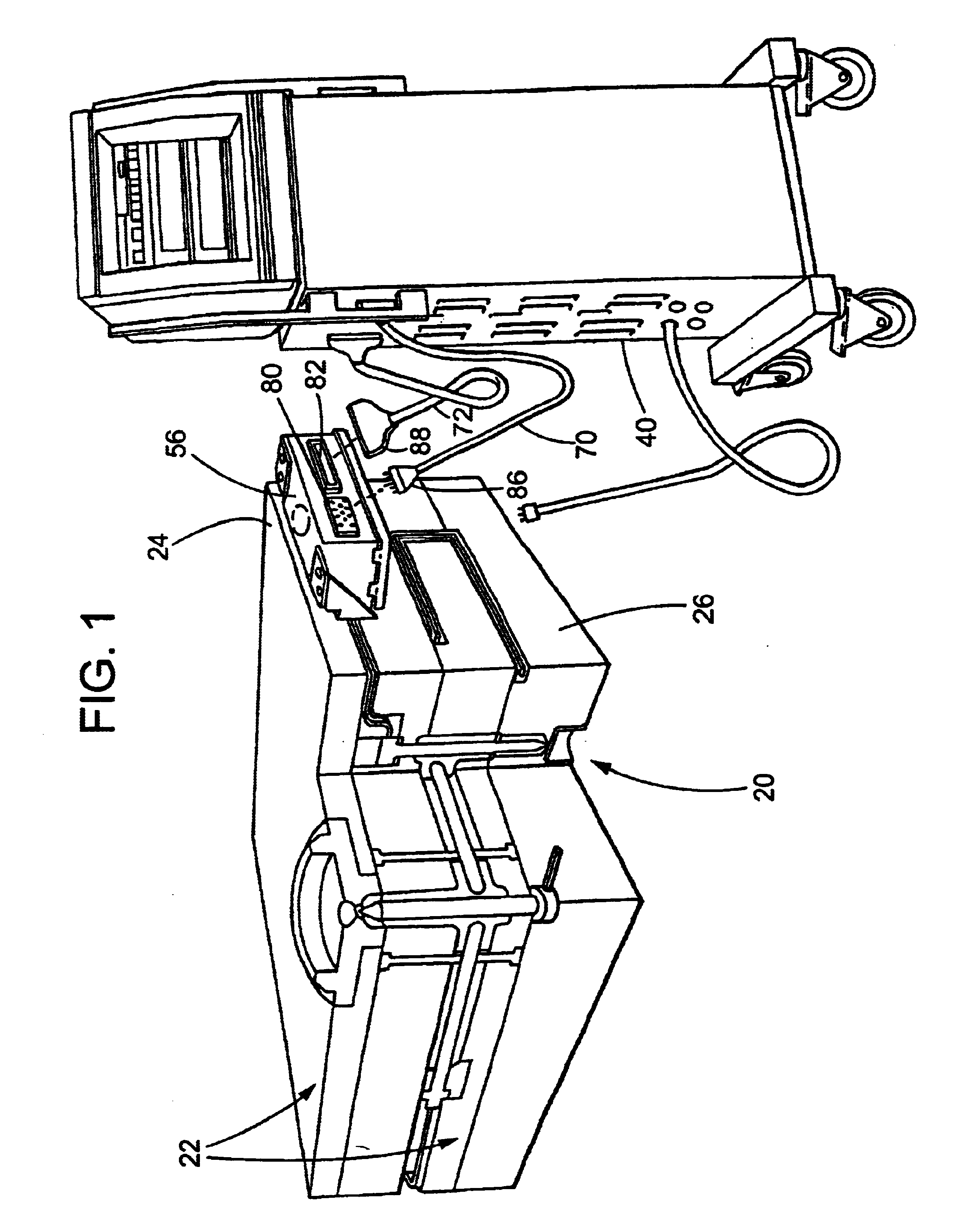
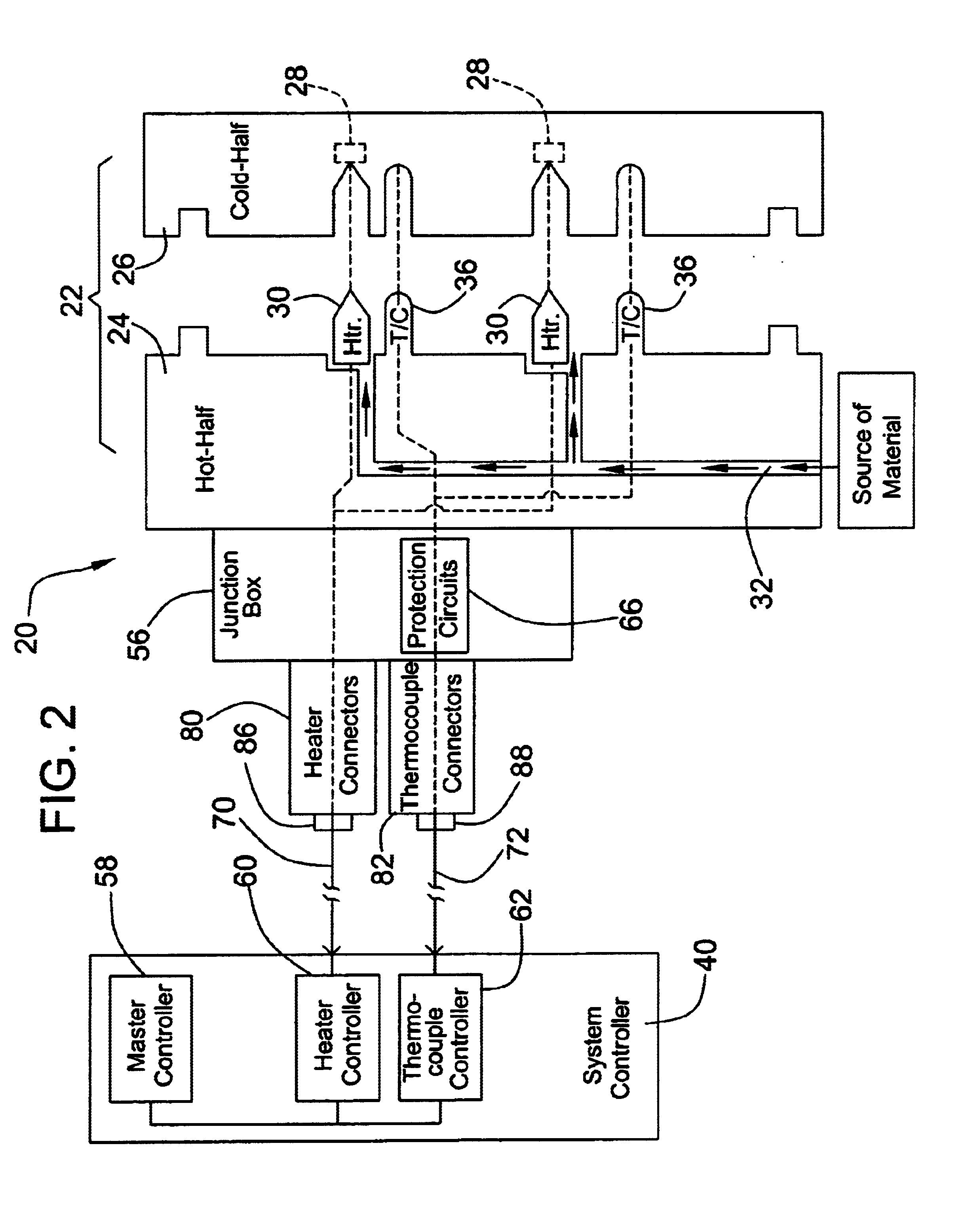
[0014]Referring now to the drawings, wherein like reference numerals refer to like elements, FIG. 1 shows a molding system generally designated 20 into which the present invention has been incorporated. The system includes a molding apparatus 22 that comprises a hot-half 24 and a cold-half 26. As is conventional, the cold-half 26 includes one or more molds 28 (FIG. 2) that have been appropriately machined or otherwise formed in the shape of the object or objects to be molded.

[0015]As best seen in FIG. 2, the hot-half 24 of the molding system includes one or more heating elements or heaters 30 suitably positioned to generate heat to maintain the liquefied injected molding material (e.g., thermoplastic) in a liquid form. To convey the liquefied material to the molds 28 in the cold-half 24, flow passages 32, which may include a manifold, is present within the hot-half 24.

[0016]For controlling the molding operation, a system controller 40 is provided. The system controller 40 includes a...


PUM

PropertyMeasurementUnit
Temperatureaaaaaaaaaa
Currentaaaaaaaaaa

Abstract

An apparatus for protecting thermocouple circuits in an injection molding system includes a protection circuit for each thermocouple pair. The protection circuit includes a resettable fuse disposed in series with each thermocouple wire for preventing high leakage current from passing through, and a capacitor connected to the two wires of a thermocouple to filter out AC line noise. The protection circuits are integrated in a junction box used to connect a heater power cable and a thermocouple control cable to the hot-half of the molding machine.

Description

FIELD OF THE INVENTION[0001]The present invention relates generally to thermoplastic injection molding technology, and more particularly to an apparatus for protecting the thermocouple circuits used in a thermoplastic injection molding machine for temperature sensing.BACKGROUND OF THE INVENTION[0002]A thermoplastic injection molding machine typically has a “cold-half” portion that contains appropriately shaped molds, and a matching “hot-half” portion that is connected to an injection system and contains a manifold or the like that provides flow passages for liquefied thermoplastic material to reach the molds in the cold-half. The hot-half of the molding machine contains multiple heaters for heating the injection molding material to maintain it in a liquid phase. To control the heating to maintaining the temperature of the molding material in an optimal range for the molding operation, the temperature in the hot half has to be closely monitored. To that end, thermocouples are typical...

Claims


Application Information

Patent Timeline
IPC IPC(8): B29C45/17B29C45/78B29C45/27
CPCB29C45/1774B29C45/27B29C45/78
Inventor KALANTZIS, PETER
Owner FAST HEAT
Learn More