
Engine exhaust heat recovering apparatus

a technology for recovering equipment and exhaust heat, which is applied in the direction of lighting and heating equipment, machines/engines, air heaters, etc., can solve the problems of hardly staying in the heat transfer medium, significant time, and rarely allowing the transfer of condensation heat at a higher efficiency, so as to minimize the degradation of components

Inactive Publication Date: 2005-07-05
HONDA MOTOR CO LTD
View PDF20 Cites 41 Cited by
  • Summary
  • Abstract
  • Description
  • Claims
  • Application Information

AI Technical Summary

Benefits of technology

[0012]The present invention has been developed in view of the above aspects and its object is to provide an engine waste heat recovering apparatus which can more effectively recover the condensation heat of exhaust gas contents generated in an exhaust gas heat exchanger.
[0021]According to the fifth feature, the water pump is disposed where the temperature of the heat transfer medium stays low. As the heat transfer medium is passed though the water pump before receiving heat from the engine, its direct contact with any component of the water pump can be avoided when heated at a higher temperature, hence minimizing the degradation of the components such as seals of the water pump.

Problems solved by technology

This causes the temperature of the heat transfer medium to hardly stay lower than the dew point W. It will hence take a significant length of time before the exhaust gas temperature drops down to the dew point W, thus rarely permitting the transfer of the condensation heat at a higher efficiency.
This issue has not yet been overcome.

Method used


Image

  • Engine exhaust heat recovering apparatus
  • Engine exhaust heat recovering apparatus
  • Engine exhaust heat recovering apparatus

Examples


Embodiment Construction

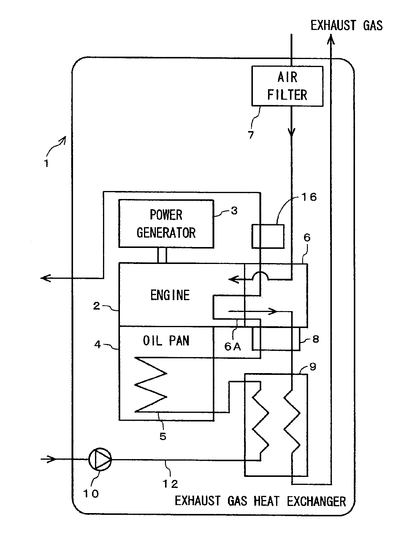
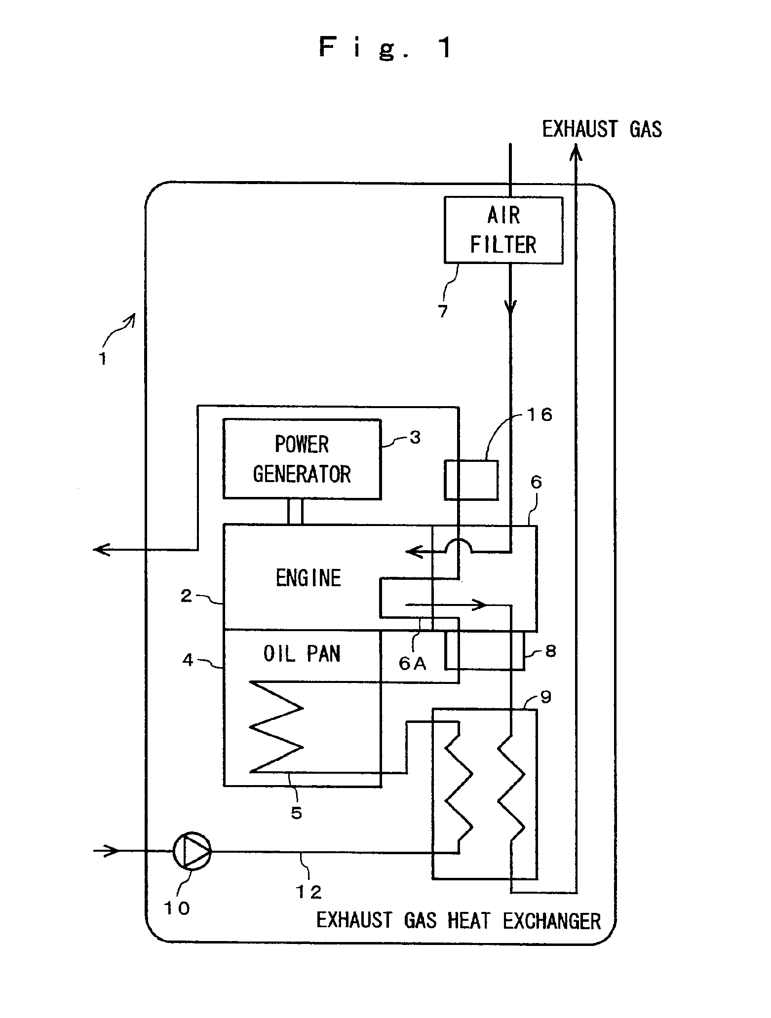
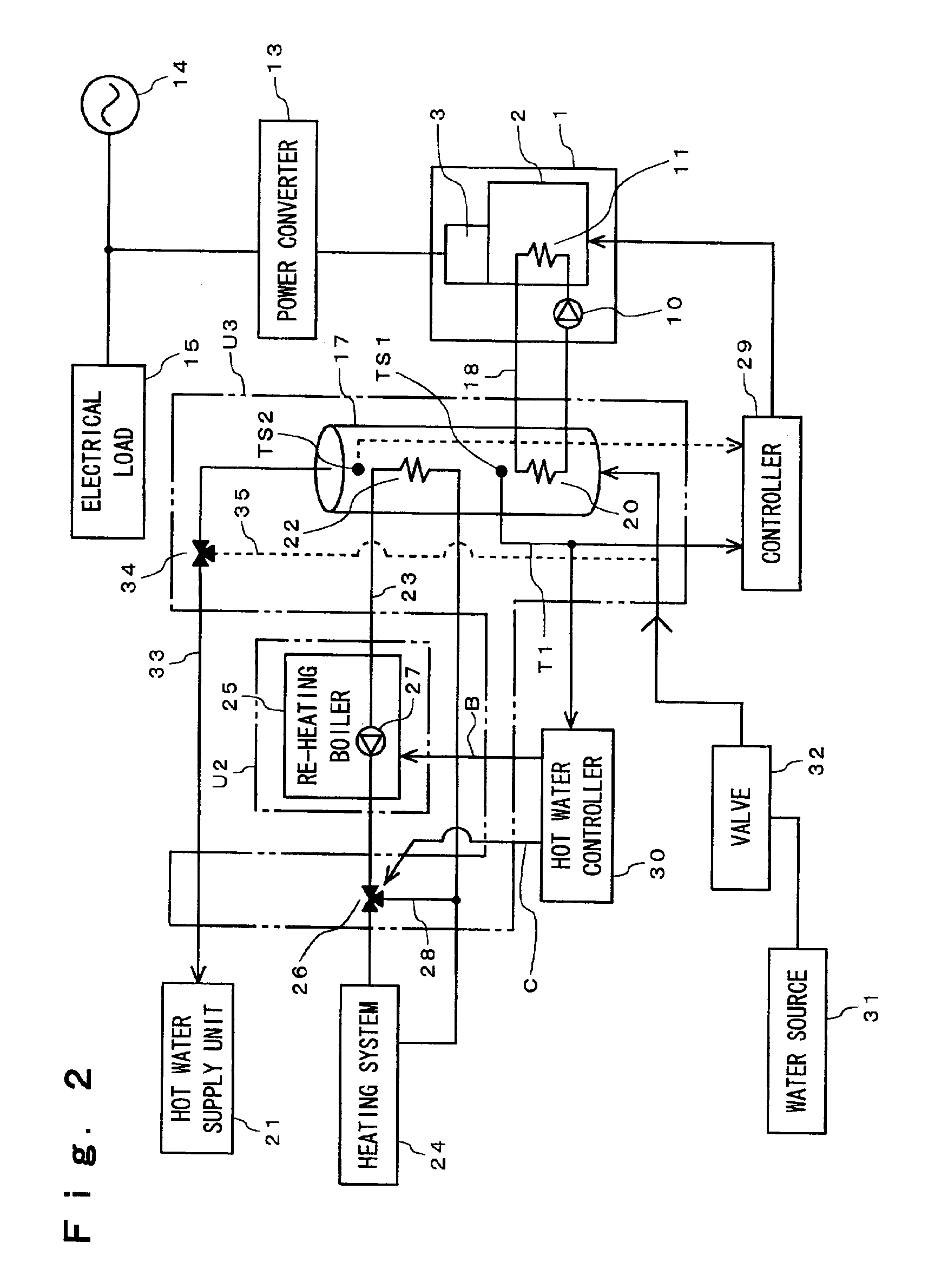
[0028]One embodiment of the present invention will be described in detail referring to the relevant drawings. Referring to FIG. 1, a waste heat recovering apparatus 1 installed in a cogeneration system is designed for recovering heat from the engine of an engine-driven power generator. The waste heat recovering apparatus 1 comprises the engine 2 and the power generator 3 mechanically connected to the engine 2. The power generator 3 generates an alternating current corresponding to the revolutions of the engine 2. The engine 2 is equipped with an oil pan 4 for storage of lubricant oil. The oil pan 4 includes an oil cooler (an oil heat exchanger) 5. The oil heat exchanger 5 transfers heat from the oil in the oil pan 4 to a heat transfer medium (a cooling water). A flow of air is introduced from an air filter 7 into a cylinder head 6 of the engine 2. An exhaust gas from the engine 2 passes through an exhaust manifold 8 and an exhaust gas heat exchanger 9 and then is discharged to the o...


PUM


Abstract

A circulating path 12 is provided for circulating a heat transfer medium across the cooling section 6A and an exhaust heat exchanger 9. The circulating path 12 is communicated to an output heat exchanger which is mounted on a hot water storage. The heat transfer medium is circulated by a pump 10 from the exhaust heat exchanger 9 to the oil heat exchanger 5 and the cooling section 6A. The heat transfer medium to be introduced into the exhaust heat exchanger 9 is so controlled in the flow rate that a temperature of the water vapor in the exhaust gas is declined to a temperature lower than the dew point. The heat transfer medium when having received heat directly from the exhaust gas and heat generated by condensation of the exhaust heat is conveyed to the cooling section 6A where its temperature soars up further.

Description

BACKGROUND OF THE INVENTION[0001]1. Field of the Invention[0002]The present invention relates to an apparatus for recovering exhaust heat from an engine and particularly, an engine exhaust heat recovering apparatus for used as a power source in a cogeneration system.[0003]2. Description of the Related Art[0004]As a variety of attempts for protection of the global environment have been proposed, energy friendly systems such as cogeneration systems for recovering the generated heat for reuse are now focused in view of the efficient usage of energy. Such a cogeneration system has an exhaust gas released at a higher temperature than that of its engine. Therefore, in the cogeneration system, a heat recovering medium (typically an engine cooling water) is introduced into the cooling section of the engine to receive the heat from an exhaust gas and then transferred to the heat exchanger where it releases the heat (See JP Patent No. 2691372 and JP Patent Laid-open Publication (Heisei)8-4586...

Claims


Application Information

Patent Timeline
Patent Type & Authority Patents(United States)
IPC IPC(8): F02G5/00F02G5/02F02G5/04F24H1/00
CPCF02G5/02Y02E20/14Y02T10/166Y10S165/916Y10S165/921Y02T10/12
Inventor TOGAWA, KAZUHIROTAKEMURA, KAZUHITO
Owner HONDA MOTOR CO LTD
Learn More