
Device and system for indicating rapid deceleration in vehicles

a technology of rapid deceleration and vehicle, applied in the direction of signalling/lighting devices, instruments, vehicle components, etc., can solve the problems of false triggers or trigger failures, false triggers, and self-contained warning devices

Inactive Publication Date: 2005-06-28
CARLSON CRAIG
View PDF5 Cites 16 Cited by
  • Summary
  • Abstract
  • Description
  • Claims
  • Application Information

AI Technical Summary

Benefits of technology

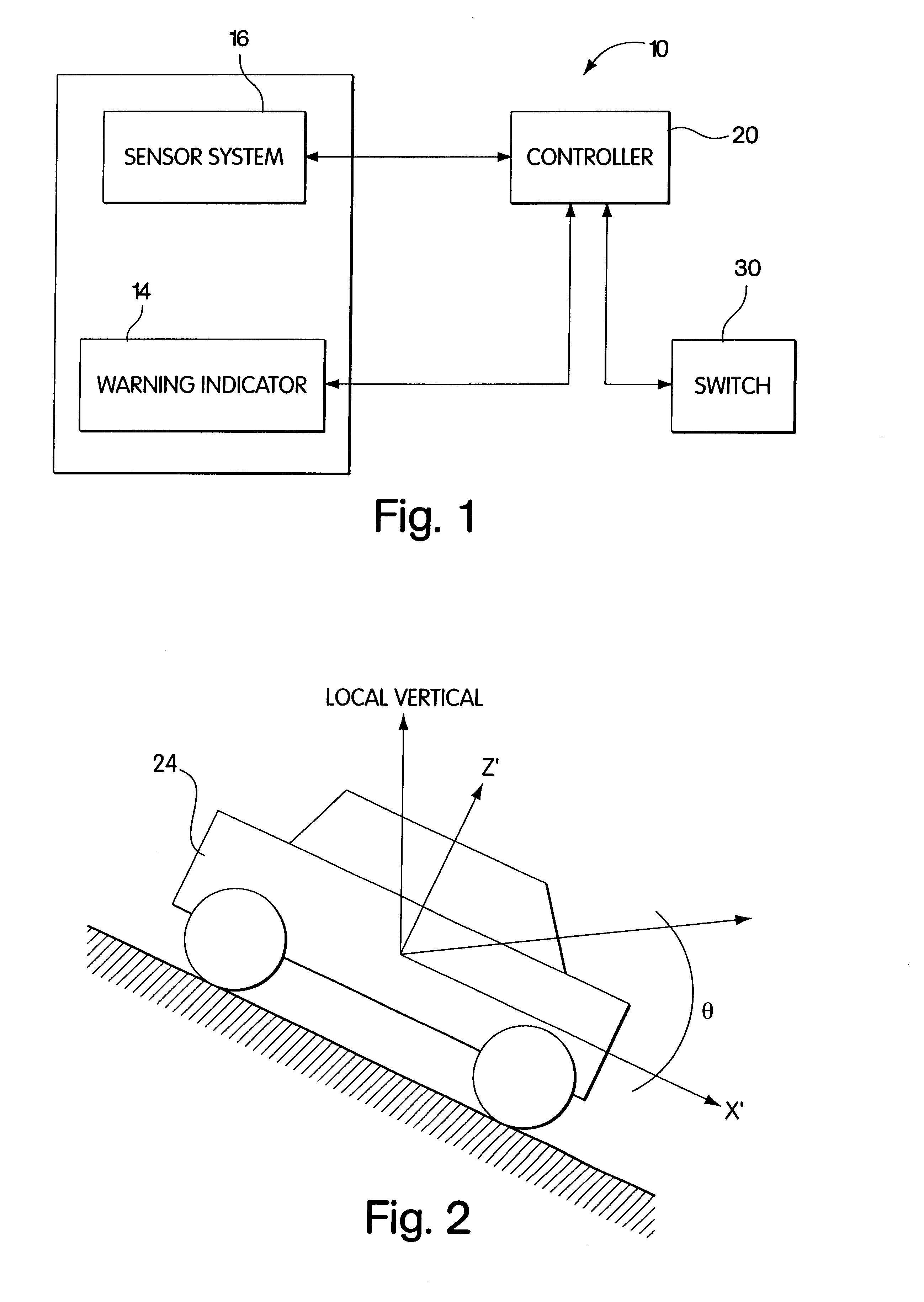
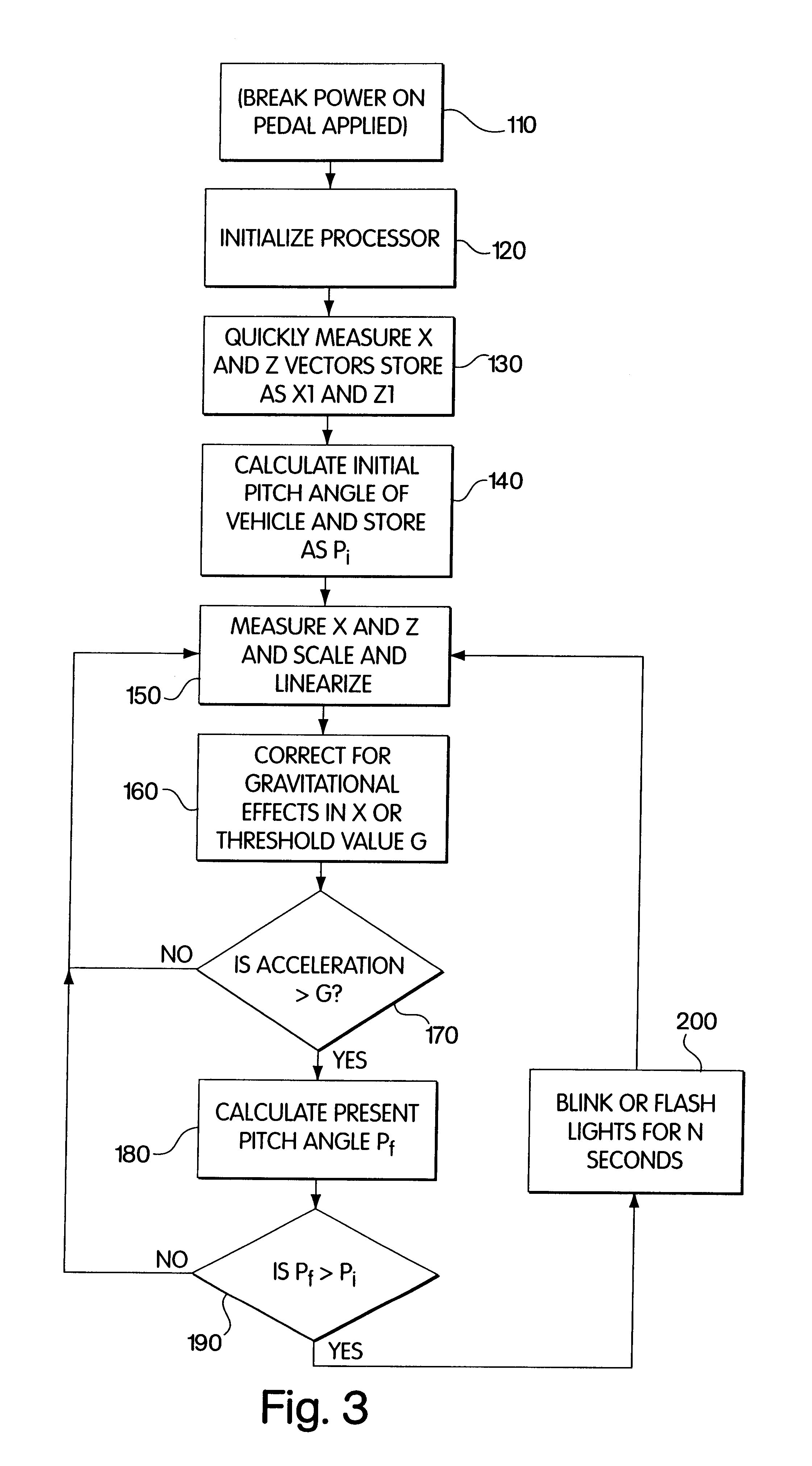
[0009]The present invention is therefore directed to a device and system to indicate an urgent deceleration that overcome the above-noted and other disadvantages of prior warning devices and warning systems. The present invention results in a warning device and system that indicate urgent deceleration independent of gravity effects. The device and system are capable of sensing acceleration in at least one direction, for example, the primary direction of vehicle motion and correcting for acceleration forces due to gravity before initiating a warning. In this respect, the Inventors have found that correcting for the acceleration due to gravity, an example of which is described herein, may be employed to render a warning device less prone to false triggering or trigger failures.
[0016]Various embodiments of the present invention provide certain advantages and overcome certain drawbacks of prior devices and systems. Embodiments of the invention may not share the same advantages and those that do may not share them under all circumstances. This being said, the present invention provides numerous advantages including the noted advantage of reducing false triggering or trigger failures.

Problems solved by technology

Some of these warning devices are self-contained and include some means for detecting deceleration in the primary direction of vehicle motion.
Because these devices only detect acceleration and only in one direction, they do not measure acceleration independent of gravitational effects and, thus, are prone to false triggers or trigger failures if the vehicle is not in a horizontal orientation when it urgently decelerates.
Thus, because of the sensed acceleration due to gravity, these warning devices will cause a false trigger or will fail to trigger such as when the vehicle is travelling up or down a slope.
However, these warning systems are not self-contained, and in addition, require a complex system of multiple sensors with extensive wiring.
As a result, these warning systems are difficult and costly to manufacture and install, particularly if retro-fitting existing vehicles.

Method used


Image

  • Device and system for indicating rapid deceleration in vehicles
  • Device and system for indicating rapid deceleration in vehicles
  • Device and system for indicating rapid deceleration in vehicles

Examples


Embodiment Construction

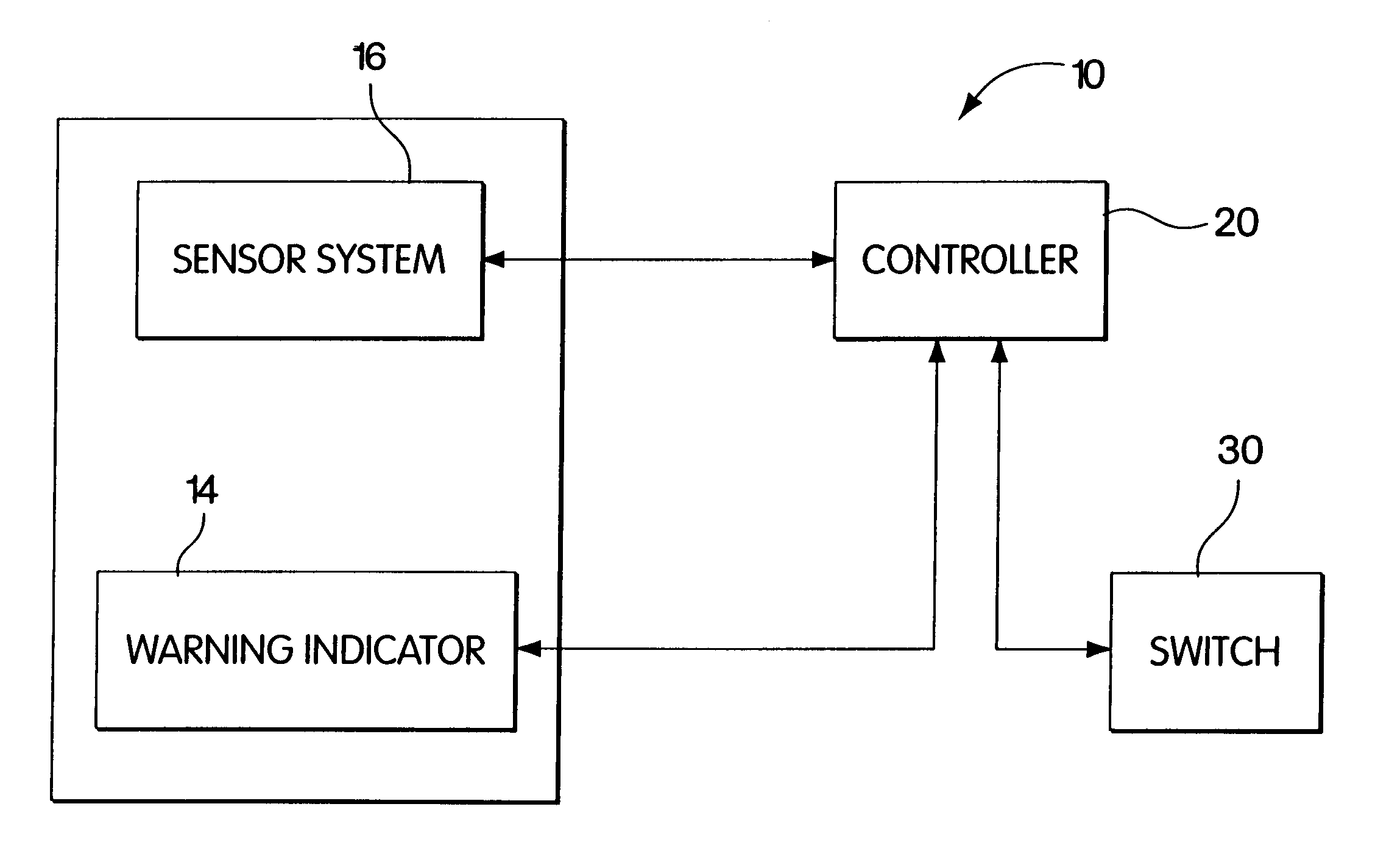
[0027]The present invention is directed to a device and system for indicating rapid deceleration in a vehicle, and more particularly to a device and system that augment existing brake indicating systems to warn the vehicle operator and / or others of an urgent deceleration condition, and method of indicating the same. The disclosed device, system, and method indicate an urgent deceleration independent of gravity effects. The device includes at least one sensor that is responsive to acceleration in the primary direction of vehicle motion. A controller communicates with the sensor and resolves the output from the sensor into an acceleration in the primary direction of vehicle motion and corrects for gravitational effects. The controller initiates a warning when the acceleration exceeds a threshold value and thereby indicates an urgent deceleration condition. It should be noted that the term “acceleration” may be used herein generically to indicate the rate of change of velocity of a mov...


PUM


Abstract

A device and system for indicating rapid deceleration to warn the operator and / or others of an urgent deceleration condition is provided. The device includes one or more sensors that are responsive to acceleration in the primary direction of vehicle motion. The controller communicates with the one or more sensors, corrects for gravitational effects, and initiates at least one warning indicator when the sensed acceleration exceeds a threshold value and thereby indicates an urgent deceleration condition.

Description

RELATED APPLICATIONS[0001]This application claims the benefit of and is a divisional of U.S. patent application Ser. No. 09 / 538,592, filed on Mar. 27, 2000, now U.S. Pat. No. 6,417,767, issued Jul. 9, 2002.BACKGROUND OF THE INVENTION[0002]1. Field[0003]The present invention relates to urgent deceleration indicating devices and systems and, more particularly to devices and systems that augment existing vehicle braking indicating devices and systems.[0004]2. Related Art[0005]Vehicles have long incorporated brake lights for warning others that the vehicle is decelerating. The brake lights are turned on when the brake pedal is depressed to indicate to the following driver that the vehicle is likely decelerating. However, the brake light merely indicates to the following driver whether the brakes are applied and give no indication as to the urgency of the braking condition or any indication of the magnitude of deceleration of the vehicle. Thus, the following driver must always be alert a...

Claims


Application Information

Patent Timeline
Patent Type & Authority Patents(United States)
IPC IPC(8): B60Q1/44
CPCB60Q1/445
Inventor CARLSON, CRAIG D.FOWLER, J. THOMAS
Owner CARLSON CRAIG
Learn More