
Toner, method for manufacturing the toner, and image forming method and apparatus using the toner

a technology of toner and manufacturing method, applied in the field of toner, can solve the problems of stripe image on half tone image, formation of undesired image, and filming problem,

Inactive Publication Date: 2005-06-28
RICOH KK
View PDF68 Cites 26 Cited by
  • Summary
  • Abstract
  • Description
  • Claims
  • Application Information

AI Technical Summary

Benefits of technology

[0027]Accordingly, an object of the present invention is to provide a toner which can be used for a long period of time without forming toner film on an image bearing member, etc. and without causing a hot offset problem even when the toner is subjected to mechanical and heat stresses, and a method for manufacturing the toner.
[0028]Another object of the present invention is to provide a toner which can produce images having good fine line reproducibility without causing background fouling, and a method for manufacturing the toner.
[0029]Yet another object of the present invention is to provide a toner having a good low temperature fixability and good high temperature preservability, and a method for manufacturing the toner.
[0030]A further object of the present invention is to provide a toner which can produce good images even when used for a small-size image forming apparatus in which a toner replenishing mechanism and a toner concentration sensor are not provided, and a method for manufacturing the toner.
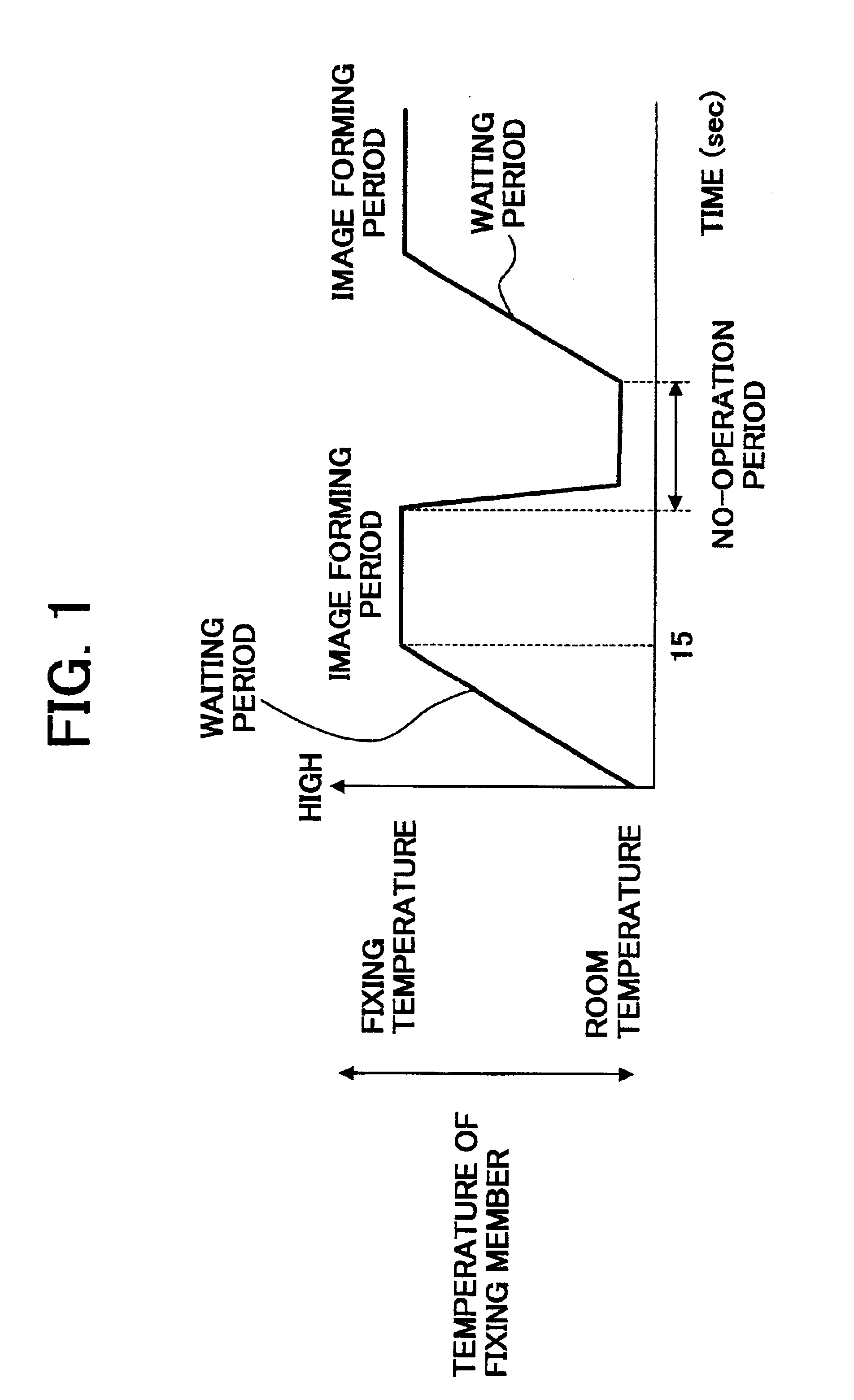
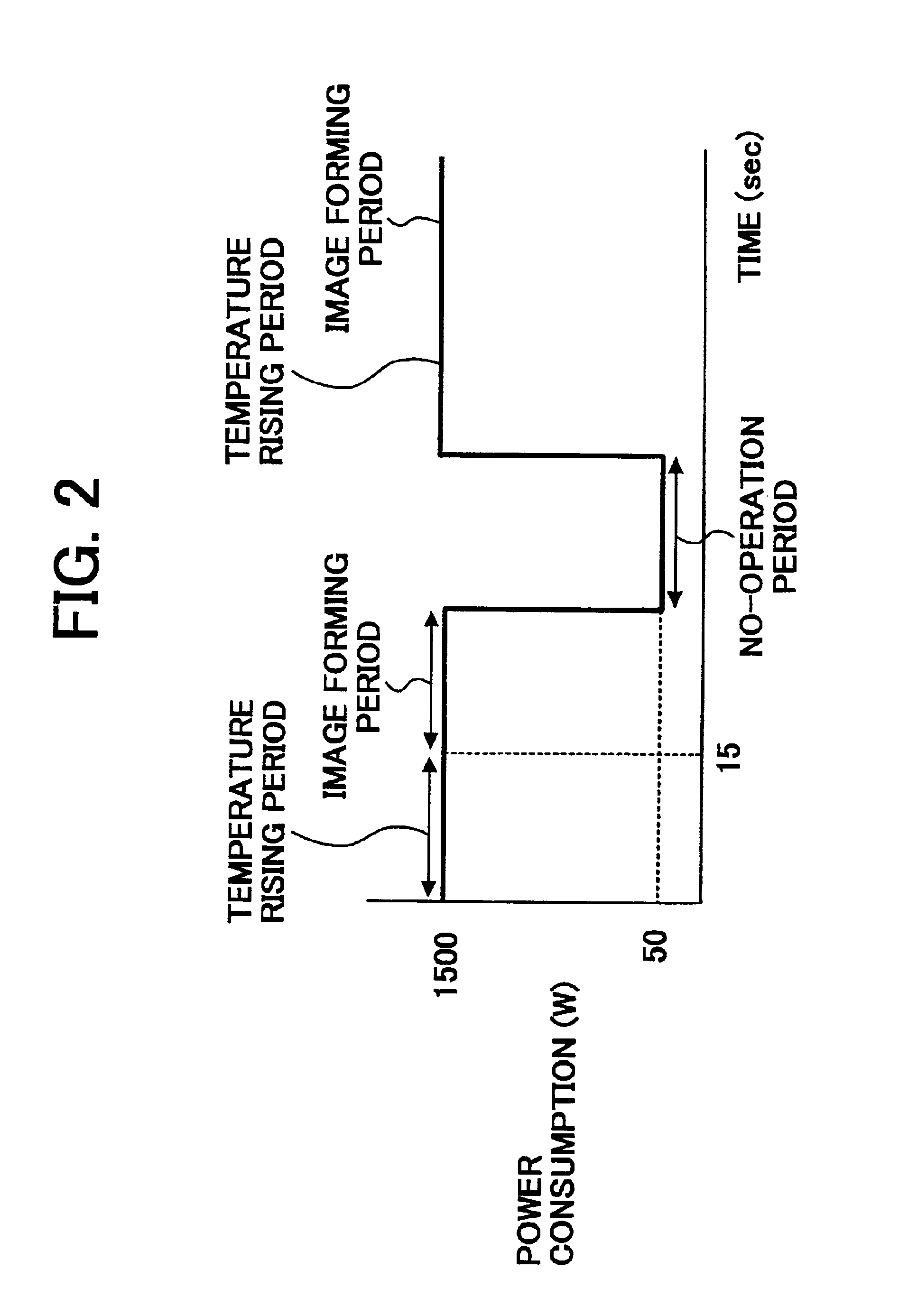
[0031]A still further object of the present invention is to provide an image forming method and apparatus by which good images can be produced at a low fixing temperature without causing a filming problem and a hot offset problem while electric power consumption and waiting period are reduced.

Problems solved by technology

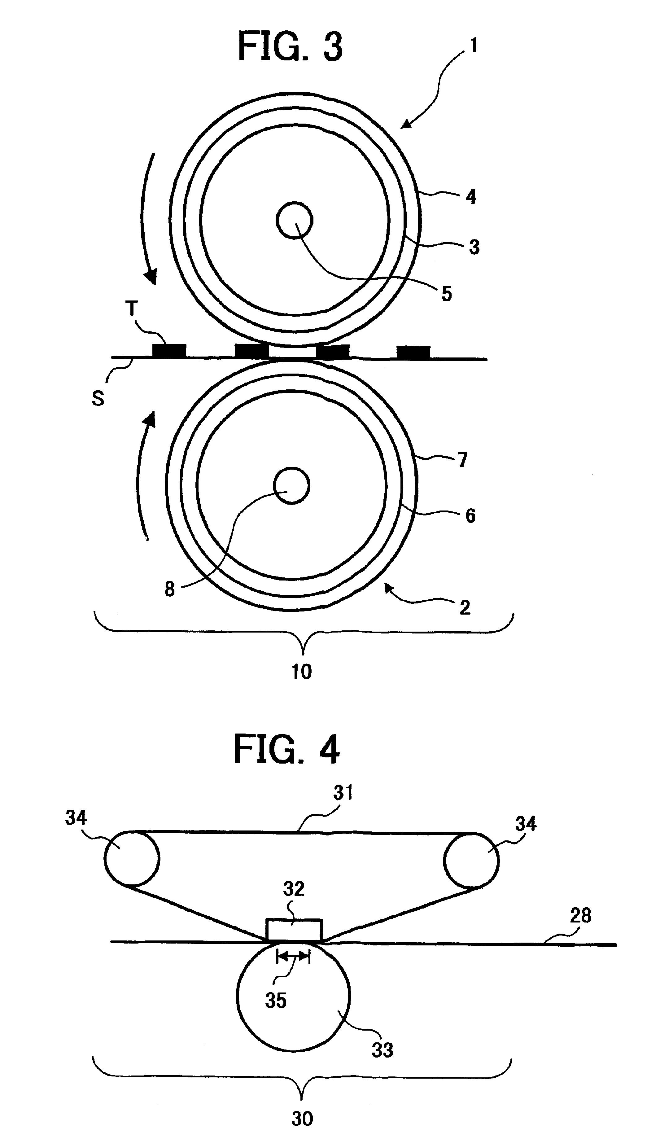
However, these heat roller fixing methods have a drawback in that a so-called offset phenomenon tends to occur such that when a toner image is fixed, part of the toner image adheres to a heat roller and the part of the toner image is re-transferred on a copy paper, resulting in formation of an undesired image.
However, when such a release agent is included in a toner, a filming problem tends to occur in that the release agent is separated from the toner when developing processes are performed and then the thus formed free release agent adheres to a photoreceptor and a developing sleeve.
The thus formed film of the free release agent gradually grows when copying processes are repeated, resulting in formation of a white stripe image on a half tone image when the film becomes too thick.
In particular, when the toner is prepared by a pulverization method, kneaded toner constituents tend to be divided at the position in which the release agent is present when pulverized, which typically has a sharp molecular weight distribution peak and is brittle, and thereby the release agent tends to be present on the surface of the resultant toner particles or tends to be present as fine powders in the resultant toner.
Therefore, when a toner having a small particle diameter is used to produce high quality images, the filming problem tends to occur.
In addition, another problem of poor fixing occurs.
In this case, the amount of heat applied from a heating member to the toner particles transferred on a recessed portion of the receiving material is very small, and therefore the toner image has poorly fixed particularly when fixed at a low temperature.
However, the method is not satisfactory because in medium-speed to high-speed image forming apparatus, the amount of heat applied to toner images is very small.
Therefore it is considered that a toner satisfying the requirements cannot be easily developed only by using known techniques.
In addition, when a toner having low temperature fixability is used, it is considered that to impart a wide fixable temperature range (i.e., a hot-offset resistance) and a good high temperature preservability to the toner become difficult.
In particular, when the image forming speed increases, the temperature of the heating member tends to decrease in fixing, resulting in decrease of the amount of heat used for fixing.
In particular, when the toners are subjected to mechanical stresses and heat stresses in image forming apparatus, the effects thereof are hardly exerted, i.e., the filming problem occurs when used for long period of time.
However, the blended resins have good compatibility (i.e., the resins can be mixed well with each other), and therefore the kneaded toner constituents cannot be easily pulverized, resulting in deterioration of productivity, and thereby the manufacturing costs increase.
However, since polyester resins typically have poor compatibility with styrene-acrylic resins, both the resins are unevenly dispersed in a toner when the resins are simply mixed mechanically.
Therefore when a toner is prepared, a colorant such as carbon black and a charge controlling agent are poorly dispersed in the toner, resulting in occurrence of fouling in the background areas of the resultant toner images.
When preparing this toner, toner constituents cannot be dispersed well because the resins are merely blended, and thereby problems occur such that background fouling is caused in the resultant images and in addition the toner image has poor blocking resistance.
However, there is no toner which has a low temperature fixability and a wide fixable temperature range (i.e., good hot offset resistance) as well as good high temperature preservability and good pulverizability, and is capable of producing images having good image qualities without producing background fouling and the filming problem even when a low pressure fixing device is used.

Method used


Image

  • Toner, method for manufacturing the toner, and image forming method and apparatus using the toner
  • Toner, method for manufacturing the toner, and image forming method and apparatus using the toner
  • Toner, method for manufacturing the toner, and image forming method and apparatus using the toner

Examples


example 1

[0200]The following components were mixed in a Henshel mixer.

[0201]

Non-linear polyester resin (A)60(acid value of 16.3 mgKOH / g, hydroxyl value of 35.1 mgKOH / g,softening point of 145.1° C., and glass transitiontemperature of 61.5° C.)Linear polyester resin (B)40(acid value of 2.1 mgKOH / g, hydroxyl value of 34 mgKOH / g,softening point of 100.8° C., and glass transitiontemperature of 60.3° C.)Carnauba wax4.5(particle diameter of 400 μm)Carbon black8(#44 from Mitsubishi Kasei Corp.)Zn (II) complex of 3,5-di-tert-butylsalicylic acid3

[0202]The mixture was heated to 130° C. and kneaded for about 30 minutes. The kneaded mixture was cooled to room temperature, and then crushed with a hammer mill to prepare particles having a particle diameter of from 200 to 400 μm. The thus prepared particles were pulverized and classified using a pulverization / classification apparatus IDS-2 (manufactured by Nippon Pneumatic Mfg. Co., Ltd.) in which a pulverizer, in which the particles were collided with a pl...

examples 2 , 3 and 4

Examples 2, 3 and 4

[0217]The procedures for preparation and evaluation of the toner and developer in Example 1 were repeated except that the particle diameter distribution of the toner particles was changed as described in Table 1 by changing the amount of the particles supplied to the pulverization / classification apparatus and the pulverizing air pressure.

example 5

[0218]The procedures for preparation and evaluation of the toner and developer in Example 1 were repeated except that the carnauba wax was replaced with a rice wax (particle diameter of 500 μm) when the toner was prepared.


PUM


Abstract

A toner including toner particles including a binder resin and a release agent, wherein when the toner is molded into a plate upon application of a pressure of 478 kg / cm2, the toner plate has a surface having a coefficient of static friction of from 0.20 to 0.40. An image forming apparatus including an image bearing member, an image developer to form a toner image on the image bearing member, an image transferer configured to transfer the toner image on a receiving material and a fixer configured to fix the toner image thereon, wherein the apparatus has a waiting time not longer than 15 seconds, and a maximum power consumption not greater than 1.5 KW and 30 W in an image forming state and in a standby state, respectively, wherein the toner is the toner mentioned above.

Description

BACKGROUND OF THE INVENTION[0001]1. Field of the Invention[0002]The present invention relates to a toner for developing an electrostatic latent image formed by electrophotography, electrostatic recording methods, electrostatic printing methods, etc. In addition, the present invention relates to a method for manufacturing the toner. Further, the present invention relates to an image forming method and apparatus using the toner.[0003]2. Discussion of the Background[0004]As for electrophotography, various methods have been disclosed, for example, in U.S. Pat. No. 2,297,691 and Japanese Patent Publications Nos. (hereinafter referred to as JPPs) 49-23910 and 43-24748. In these methods, a copy image is typically formed by the processes of forming an electrostatic latent image on a photoreceptor including a photosensitive material by one of various latent image forming methods; developing the latent image with a toner; transferring the toner image on a receiving material such as papers; an...

Claims


Application Information

Patent Timeline
Patent Type & Authority Patents(United States)
IPC IPC(8): G03G9/087G03G9/08G03G9/083G03G9/097G03G9/10G03G15/08G03G15/20
CPCG03G9/08782G03G9/0808
Inventor HIGUCHI, HIROTOSASAKI, FUMIHIROIWAMOTO, YASUAKINAKAI, HIROSHISHU, BINGMATSUDA, HIROAKIKONDO, MAIKO
Owner RICOH KK
Learn More