Eureka AIR delivers breakthrough ideas for toughest innovation challenges, trusted by R&D personnel around the world.

Wearable protective system having protective elements

Inactive Publication Date: 2005-06-28
WARWICK MILLS INC
View PDF18 Cites 36 Cited by
  • Summary
  • Abstract
  • Description
  • Claims
  • Application Information

AI Technical Summary

Benefits of technology

[0007]An illustrative embodiment incorporating aspects of the invention provides a protective covering system resistant to penetration of an object, which can be configured as a wearable garment. The protective system includes a plurality of matrix layers, and a plurality of protective elements. At least two of the plurality

Problems solved by technology

The demands placed on such protective systems are high.
Although some protective systems have been developed to counter these threats, the systems do not meet other requirements of weight and / or flexibility.
For example, protective vests including large metal or ceramic plates may provide protection against likely threats, but are typically heavy and inflexible.
The close spacing and inflexibility of the metal tiles makes this vest unacceptable to some users because it is too heavy and stiff for comfortable wear as other than an outer vest or protective garment, and is not suitable for concealable use.
As with other armors of this type, the described protective garments were not accepted commercially because of their high weight and inflexibility.

Method used


Image

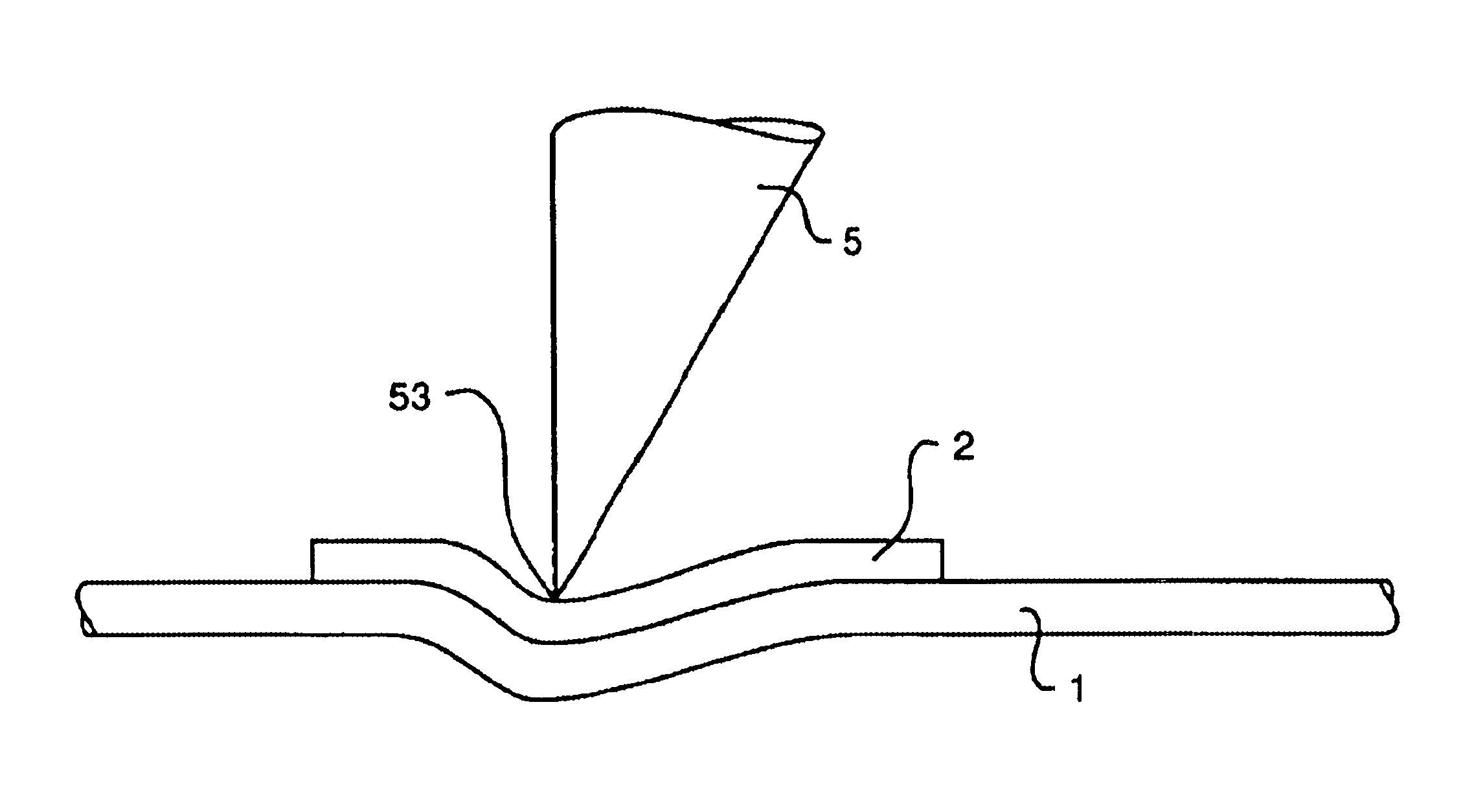
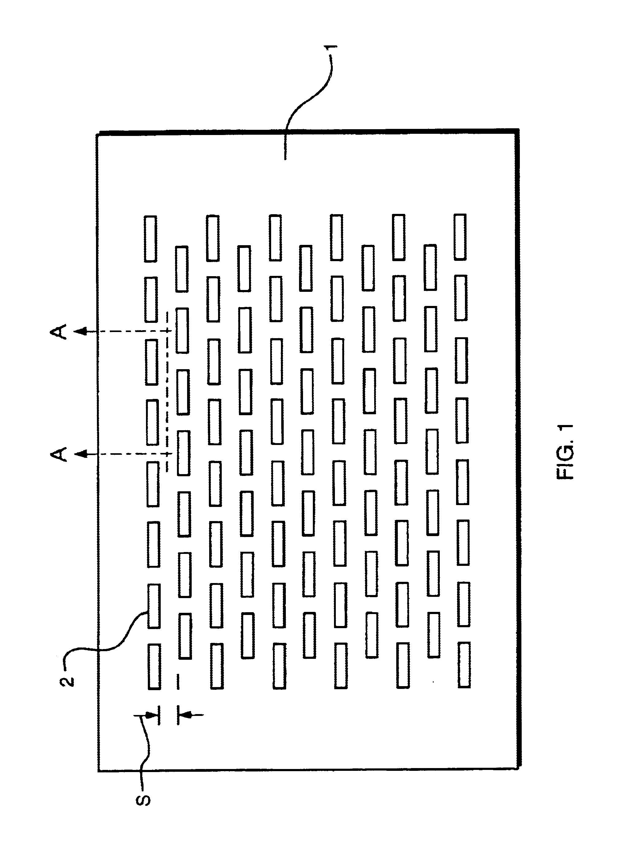
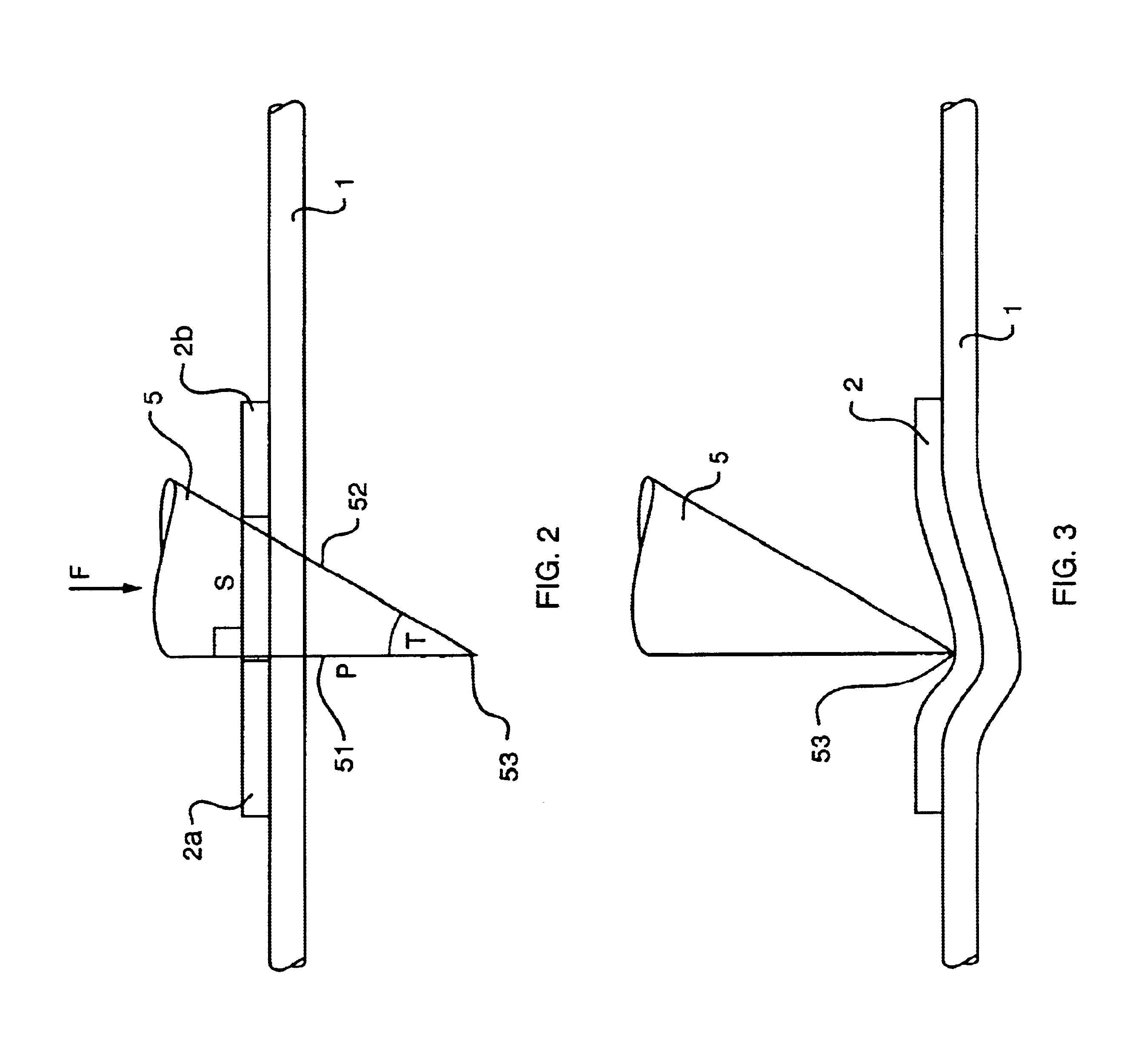
  • Wearable protective system having protective elements
  • Wearable protective system having protective elements
  • Wearable protective system having protective elements

Examples


Embodiment Construction

[0027]Illustrative embodiments of the invention provide a protective covering system that is resistant to the penetration of objects that present a relatively small impact area upon impact with the protective system. For example, the object may be a knife, bullet, ice pick or other object that can present a relatively small impact area. As one example, when a knife is moved in a stabbing-type motion, the knife may impact a protective covering system with the tip of the knife. The protective covering system may also provide protection against objects that present a broader impact area, such as blunt striking objects like clubs, and other objects, such as knives that impact the protective system in a slashing-type direction where an extended length of the knife blade edge impacts the system. Illustrative embodiments of the invention may be incorporated into a wearable garment, such as a vest, jacket, glove, helmet, pants, boots, or other garment, or used in other applications, such as...


PUM

PropertyMeasurementUnit
Lengthaaaaaaaaaa
Fractionaaaaaaaaaa
Fractionaaaaaaaaaa

Abstract

A protective covering system having high-flexibility and low areal density characteristics. In one aspect of the invention, the protective system includes a plurality of metallic staples or wire elements secured to multi-layer matrix including woven fibers, the layers being oriented at cross angles to provide a grid-like pattern of protective elements. In one aspect of the invention, protective elements provide a coverage area of less than 90% and as little as 40% of total surface area. In one aspect of the invention, protective elements may be mechanically secured to a matrix by a puncture and crimp process. In another, wire elements may be attached or woven into one or more matrix layers.

Description

[0001]This application is a non-provisional of U.S. provisional application Ser. No. 60 / 255,289 filed Dec. 13, 2000 and relates and claims priority for all purposes.FIELD OF THE INVENTION[0002]The invention relates to protective systems, such as body armor, including protective elements.BACKGROUND OF THE INVENTION[0003]There is a strong desire on the part of law enforcement, military organizations and others to increase the protection provided by protective systems, such as body armor. The demands placed on such protective systems are high. For example, wearers of body armor encounter a variety of different threats, such as hand guns, commercial and hand-made knives, ice picks, needles and others. Although some protective systems have been developed to counter these threats, the systems do not meet other requirements of weight and / or flexibility. For example, protective vests including large metal or ceramic plates may provide protection against likely threats, but are typically hea...

Claims


Application Information

Patent Timeline
IPC IPC(8): F41H5/04F41H5/00
CPCF41H5/0492Y10T428/24132Y10S428/911Y10S428/902Y10T442/3179Y10T442/56Y10T442/3504Y10T442/3122Y10T428/249924
Inventor HOWLAND, CHARLES
Owner WARWICK MILLS INC
Why Eureka
Eureka Blog
Learn More