
Method and apparatus for reducing interference in a data stream using autocorrelation derived equalization

a technology of autocorrelation and data stream, applied in pulse technique, amplitude demodulation, instruments, etc., can solve the problems of limited usable bandwidth of fiber, inability to recover transmitted signals without errors by standard transceivers, and limited data transmission over long distances of optical fiber. , to achieve the effect of reducing the effect of channel response and channel respons

Inactive Publication Date: 2005-06-21
II VI DELAWARE INC
View PDF4 Cites 47 Cited by
  • Summary
  • Abstract
  • Description
  • Claims
  • Application Information

AI Technical Summary

Benefits of technology

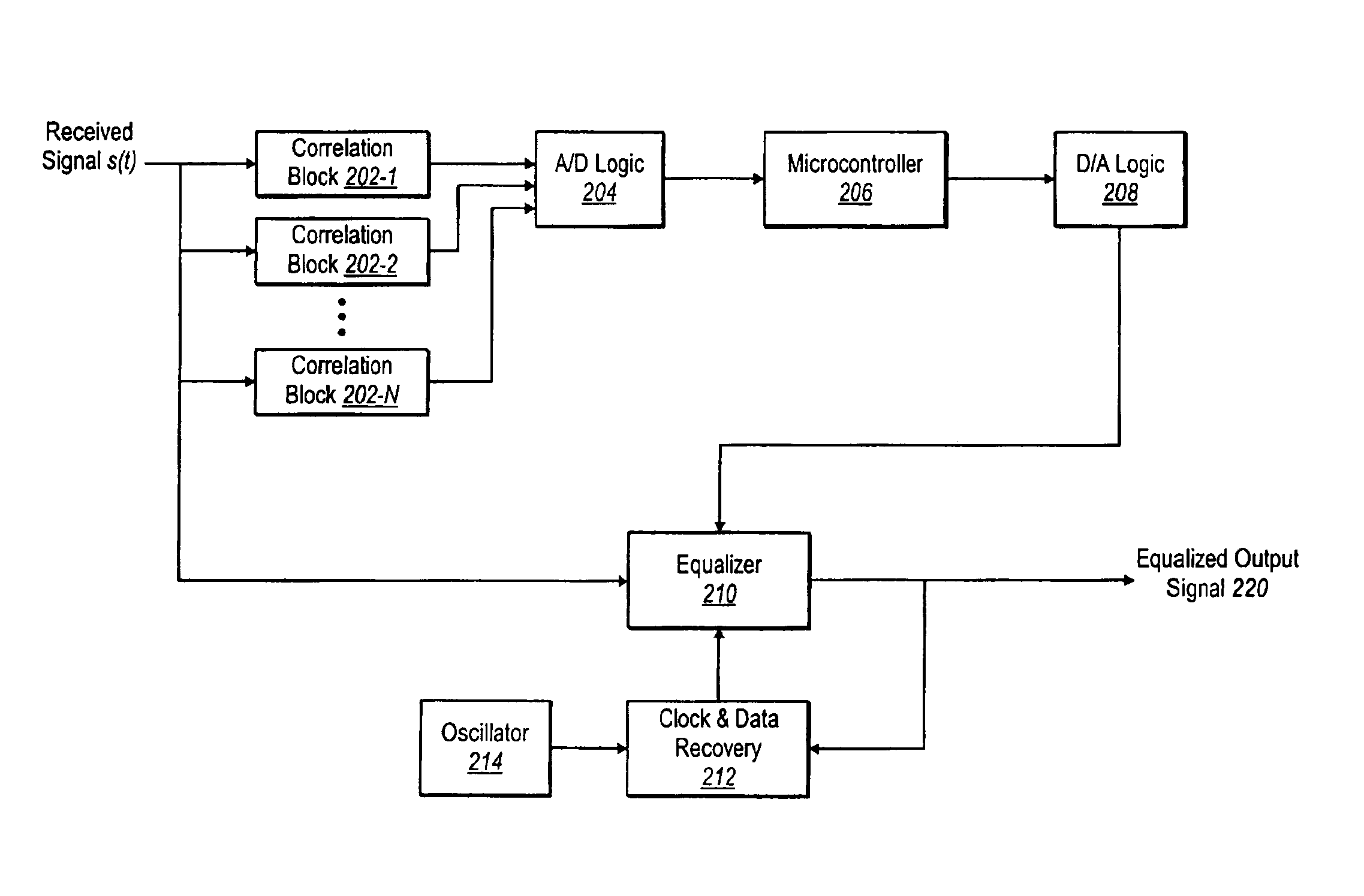
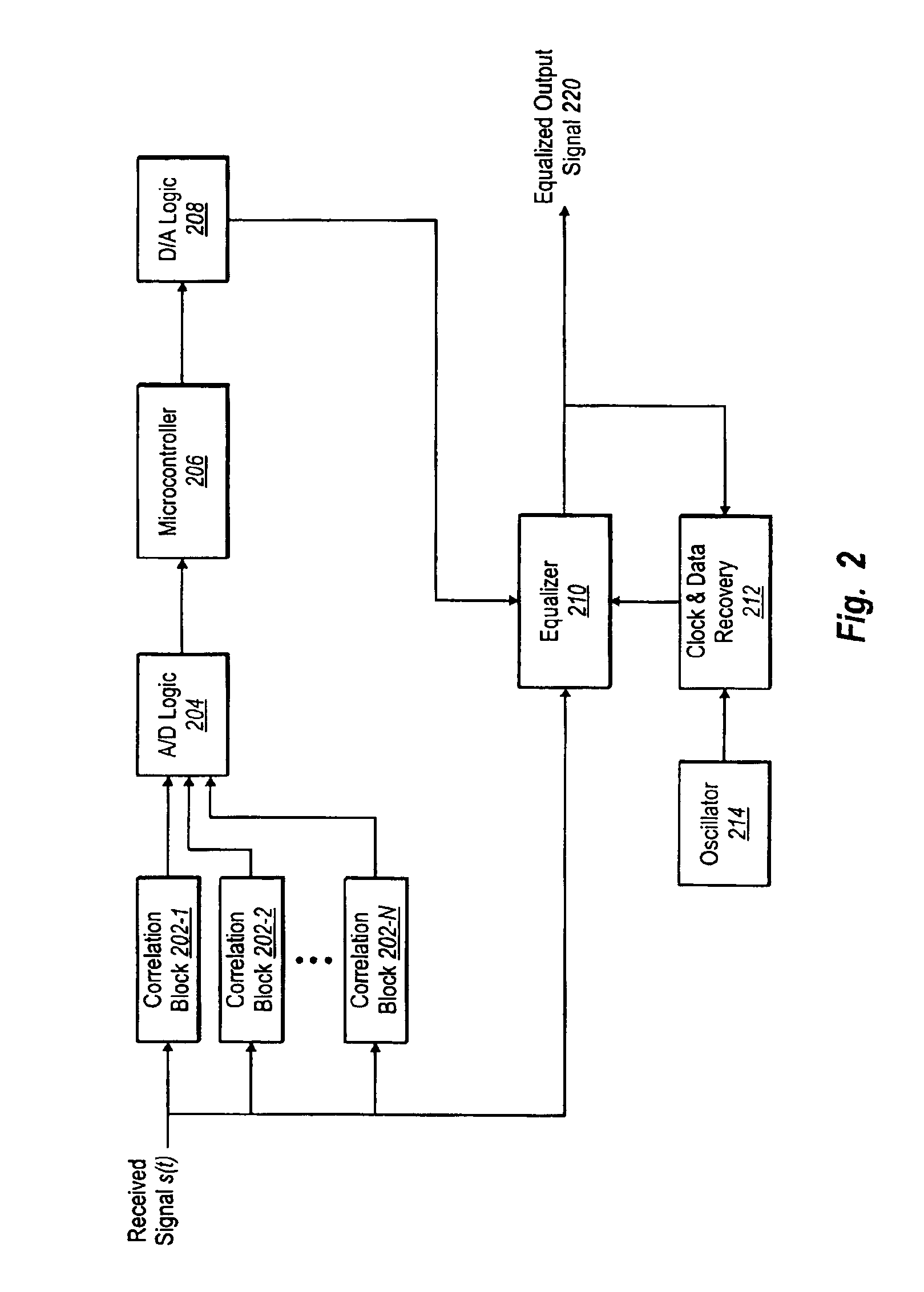
The patent describes a method and system for reducing the effects of a channel response in an output signal. This is achieved by measuring the output signal, calculating a correlation statistic, estimating the channel response, and generating filter coefficients to equalize the output signal. The system includes a correlation block and a microcontroller to predict and optimize the channel response. The technical effects of this invention include reducing the amount of hardware needed and not requiring a training sequence for the adaptive filter.

Problems solved by technology

Transmission of data over long distances of optical fiber is limited by interference, such as from multimode dispersion, which limits the usable bandwidth of the fiber.
Different modes in a multimode fiber travel at different velocities, which can cause a transmitted signal to be unrecoverable without errors by a standard transceiver.
This is particularly problematic for fiber optic systems operating at high data rates over long distances—for example, for fiber for 1310 nm light with 10 Gb / s communications over a distance of 300 m. For this type of system, the usable distance may lie in the range of 60 to 100 meters.
But, this is far short of the IEEE standard for 10 Gb Ethernet which, specifies a distance of 300 m for multimode fiber.
One particular complication of determining the channel response is that it is time variant, with a time constant thought to be one millisecond or greater (but not known exactly).
The channel response variation results from interference between different modes of the fiber, and may be caused by, for example, motion of the fiber or thermal variations along the fiber's length.
Also, because fibers are often installed in the ceiling of office buildings, they are generally bent around ventilation ducts, which can lead to the coupling of different modes.
One problem of an adaptive equalizer, however, is that it should be initialized with initial filter coefficients to recover the data clock and to converge on the data signal.
Requiring a training sequence presents an interoperability problem, however, because a transmitter in a device might not know it needs to send a training sequence before initiating communications.
The key disadvantage of this approach is high power consumption—e.g., an A / D converter at this speed typically requires at least one watt of power, and the digital circuitry typically requires another watt.
This high-power consumption precludes the use of this approach in most datacom transceivers.
There are several disadvantages to this approach, however.
First, because the amount of analog circuitry required is extensive, the overall design project becomes complex and prone to error.
Second, and more intractable, is the problem of false lock, or failure to converge, without the use of a training sequence.
And, the use of a training sequence causes the interoperability problem mentioned above.
While this implementation avoids the high-power problems of the pure-digital approach and the design complexity of the pure-analog approach, there is still the vexing problem of obtaining convergence without a training sequence.

Method used


Image

  • Method and apparatus for reducing interference in a data stream using autocorrelation derived equalization
  • Method and apparatus for reducing interference in a data stream using autocorrelation derived equalization
  • Method and apparatus for reducing interference in a data stream using autocorrelation derived equalization

Examples


Embodiment Construction

[0025]In this description, the term “subset” is used generally to mean a portion of something, up to and including the entirety of the something.

[0026]A. Mathematical Model of the Fiber Transmission System

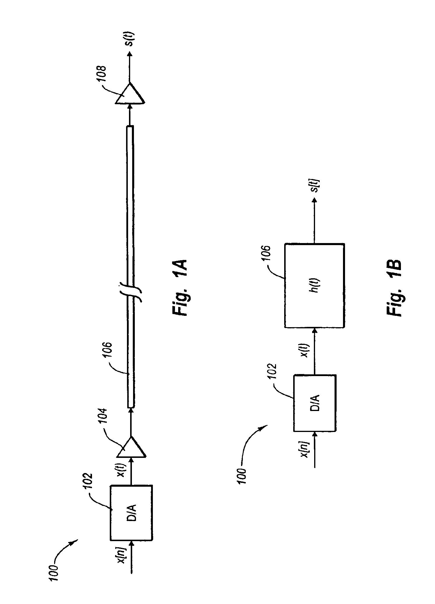
[0027]Referring to FIG. 1A, a typical multimode optical transmission system 100 includes a digital-to-analog (D / A) converter 102, a transmission amplifier 104, a multimode fiber 106, and a receiver 108. An input bit sequence x[n] is provided to the D / A converter 102, which converts the sequence to an input signal x(t). The transmission amplifier 104 transmits the input signal on the multimode fiber. At the receiving end of the system, the receiver 108 determines an output signal s(t). Ideally, the input bit stream x[n] can be unambiguously recovered from this output signal s(t). In practice, however, this is difficult due to the distorting effects of amplification by amplifier 104, propagation through fiber 106, and reception by receiver 108 of x(t).

[0028]To determine a mathematica...


PUM


Abstract

Compensating for channel response in communications systems. An equalizing system includes a correlation block to calculate a correlation statistic from a received signal. The correlation statistic is used by a microcontroller to predict a channel response that includes a number of expansion coefficients. A steepest decent procedure is applied to the expansion coefficients. The steepest decent procedure may include, for example, a bias, or zeroing expansion coefficients by trial and error to remove ghost peaks. The steepest decent procedure produces a number of optimized expansion coefficients. The optimized expansion coefficients are used to create a number of filter coefficients. The filter coefficients are applied to an equalizer. The equalizer compensates for effects of the channel response to produce an equalized output signal.

Description

CROSS-REFERENCE TO RELATED APPLICATIONS[0001]This application is a continuation in part of, and claims the benefit of prior U.S. application Ser. No. 10 / 419,023, titled METHOD AND APPARATUS FOR REDUCING INTERFERENCE IN AN OPTICAL DATA STREAM USING DATA-INDEPENDENT EQUALIZATION filed Apr. 17, 2003, which is incorporated herein by reference.BACKGROUND OF THE INVENTION[0002]1. The Field of the Invention[0003]The present invention relates to reducing interference in a data stream, and more particularly, to a system and method for reducing interference by equalizing a data-stream with an adaptive equalizer.[0004]2. Description of the Related Art[0005]Transmission of data over long distances of optical fiber is limited by interference, such as from multimode dispersion, which limits the usable bandwidth of the fiber. Different modes in a multimode fiber travel at different velocities, which can cause a transmitted signal to be unrecoverable without errors by a standard transceiver. This i...

Claims


Application Information

Patent Timeline
Patent Type & Authority Patents(United States)
IPC IPC(8): H03H7/30H03D1/00H03D1/04H04L7/00H04B1/10H04L27/06G02BH04B10/18
CPCH04B10/2543
Inventor LEONOSKY, THOMAS J.
Owner II VI DELAWARE INC
Learn More