
Information recording method, information recording medium, and information recording apparatus

a technology of information recording and information recording medium, which is applied in the field of information recording method, information recording medium and information recording apparatus, can solve the problems of insufficient satisfaction of conditions, limitation of realizable recording density, and optimization of respective energy levels, and achieves the effect of improving density and selecting easily and accurately

Inactive Publication Date: 2005-06-21
HITACHI CONSUMER ELECTRONICS CORP
View PDF8 Cites 4 Cited by
  • Summary
  • Abstract
  • Description
  • Claims
  • Application Information

AI Technical Summary

Benefits of technology

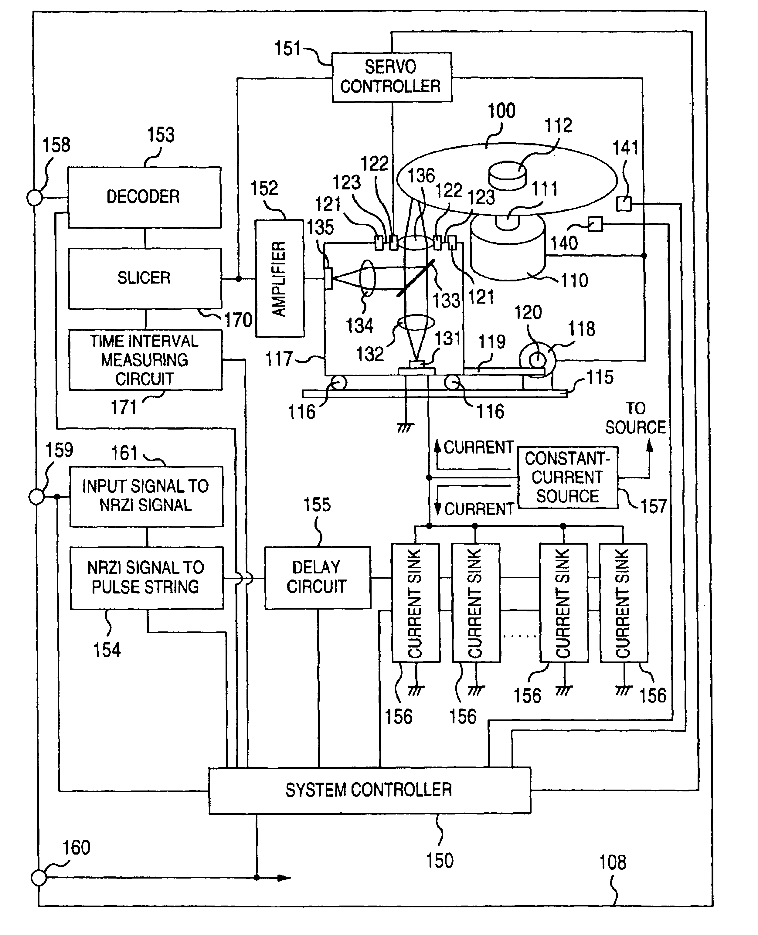
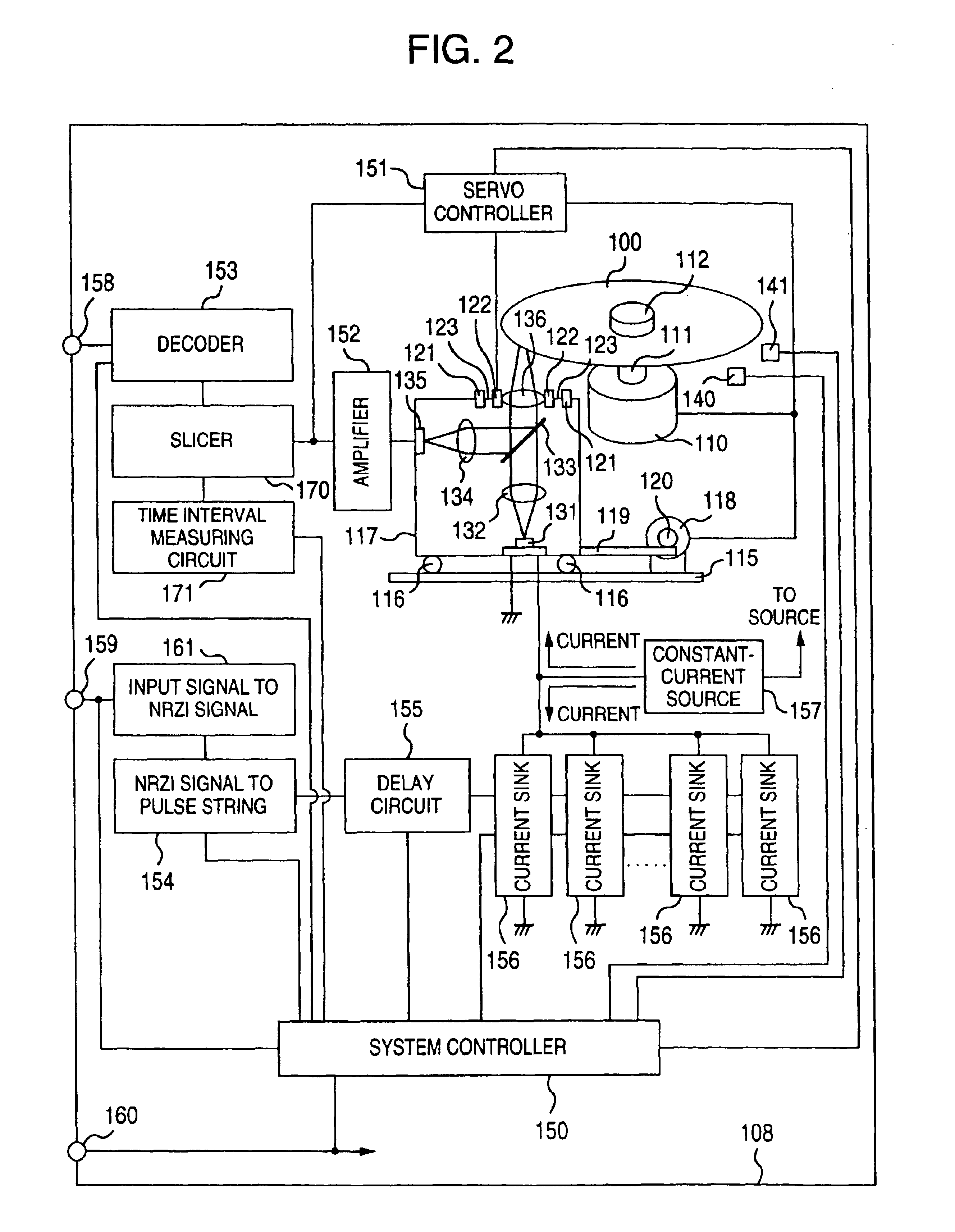
[0013]A first object of the present invention is to solve the aforementioned first problem, that is, to provide an information recording method and an information recording apparatus in which the accurate recording can be performed to improve density more greatly by use of the same spot diameter as that in the prior art while the compatibility with the prior art is kept. Particularly, the first object of the present invention is to provide an information recording method in which four energy levels for use in forming recording marks are selected easily and accurately, and to provide an information recording apparatus using the information recording method.
[0014]A second object of the present invention is to solve the aforementioned second problem, that is, to provide an information recording method and an information recording apparatus in which such unsuitable recording power levels as mentioned above are prevented from being set so that the stable recording / reproducing can be normally performed.

Problems solved by technology

However, in various types of known recording waveforms, it is impossible to satisfy the condition sufficiently.
Accordingly, there is a limitation in realizable recording density.
Increase of the number of energy levels, however, brings about a problem of how to optimize the respective energy levels.
But, there is a problem that the procedure of optimizing the energy levels is complicated because energy balance becomes delicate and the number of energy levels is large (first problem).
The absolute values of the recording power levels, however, may change due to the individual difference of the information recording apparatus, or due to the environmental change or aging of the information recording apparatus.
Accordingly, it may be impossible to perform appropriate recording on the basis of the timing information written on the disk.
In such a case, the reproductive jitter at the time of recording / reproducing the random pattern becomes worse than the expected value.
As a result, if the recording power levels are determined on the basis of the jitter of the random pattern in the same manner as that in the prior art, there is a possibility that the recording power levels may be set to unsuitable values.
If the recording is performed on the basis of the unsuitable recording power levels, there is a fear of reduction in reliability of recording / reproducing, for example, the recording becomes unstable, the already written information is erased due to cross-erasure, and so on (second problem).
Further, when the space between the recording marks is short, the recording marks cannot be resolved by the reading light spot, so that the shifting of the recording mark edge position occurs in the reproductive signal waveform.
However, when high-density recording is to be performed by use of the phase-change medium such as a DVD-RAM with the recording capacity of 4.7 GB, there is a problem that the procedure for determining the irradiation timing of the recording pulses in detail is not always clear (third problem).

Method used


Image

  • Information recording method, information recording medium, and information recording apparatus
  • Information recording method, information recording medium, and information recording apparatus
  • Information recording method, information recording medium, and information recording apparatus

Examples


first embodiment

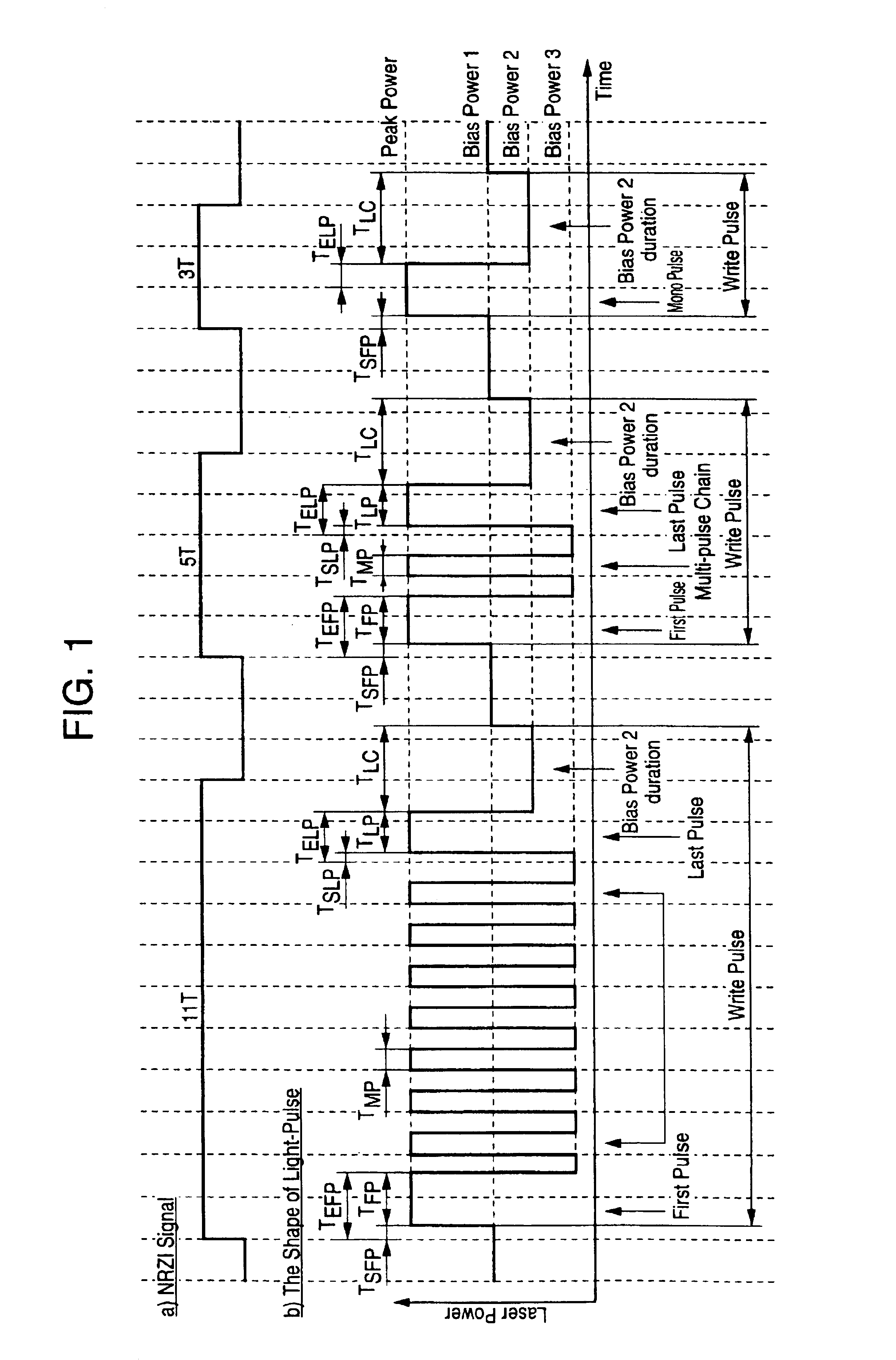
[0198]Referring first to FIG. 1, there is shown an example of the change of a power level of an energy beam, which is irradiated on the recording medium when information is recorded thereon, with the passage of time. The way of changing the power level with the passage of time in the recording of information will be hereinafter referred to as “write strategy” or “recording strategy”. The write or recording strategy will be described with respect to DVD-RAM as an example.

[0199]In the case of DVD-RAM, each of the shortest mark and the shortest space is 3T long (three times as long as T) when T is a time interval of a reference clock pulse signal for recording / reproducing. Further, each of the largest mark and the largest space is generally 11T long. As a special pattern, 14T-long mark and space may be provided.

[0200]When an NRZI signal is given as information to be recorded time-sequentially on a recording medium, the NRZI signal is converted into a time-sequential change of the power...

second embodiment

[0245]An information recording method according to a second embodiment of the present invention will be described below with reference to FIG. 1.

[0246]As described above, it is thought of that the initial values of Peak Power, Bias Power 1, Bias Power 2 and Bias Power 3 are determined on the basis of the recommended values which are read from the control data zone information track of the recording medium.

[0247]Assume now that the recording medium, the recording power levels for the recording medium and the look-up tables for the edge shifting are given to the information recording apparatus. The values of the recording power levels and look-up tables may be those which are read from a predetermined place of the recording medium, or may be obtained by some method in the information recording apparatus. The information recording apparatus performs the recording using the recording power levels and the look-up tables. However, the given recording power levels and the given look-up tab...

third embodiment

[0267]An information recording method according to a third embodiment of the present invention will be described below. A mark string to be recorded in the recording medium will be described first with reference to FIGS. 5A and 5B.

[0268]FIG. 5A shows a second state (hereinafter referred to as “mark”) and a first state (hereinafter referred to as “space”) of the recording medium both of which are recorded on the recording medium. Let T be the period of a clock signal (recording timing generating clock signal) which operates with a reference frequency when marks and spaces are recorded. Let v be the velocity of the energy beam relative to the recording medium. A small recording pattern “A” (first small recording pattern) is composed of a mark (first mark) with length avT, a space (first space) with length ivT following the first mark, a mark (second mark) with length mvT following the first space, a space (second space) with length jvT following the second mark, and a mark (third mark...


PUM

PropertyMeasurementUnit
diameteraaaaaaaaaa
lengthaaaaaaaaaa
lengthaaaaaaaaaa

Abstract

An information recording method using a recording medium having a first state by a first power level of an energy beam and a second state by a second power level of the energy beam higher than the first power level. When a period of a recording time generating clock in a recording mode is T, and a relative velocity of the energy beam and the recording medium is V, the method includes forming a sequence of the second state with length avT (first mark), the first state with length ivT (first space) following the first mark, the second state with length mvT (second mark) following the first space, the first state with length jvT (second space) following the second mark and the second state with length bvT (third mark) following the second space as a first small recording pattern.

Description

CROSS REFERENCE TO RELATED APPLICATION[0001]This is a continuation of U.S. application Ser. No. 09 / 415,263, filed Oct. 12, 1999, now U.S. Pat. No. 6,650,607, the subject matter of which is incorporated by reference herein.BACKGROUND OF THE INVENTION[0002]1. Field of the Invention[0003]The present invention relates to an information recording method, an information recording medium and an information recording apparatus, using a recording medium in which information can be recorded by energy beam irradiation. Particularly, it relates to an information recording method having an excellent effect on a phase-change optical disk, an information recording medium, and an information recording apparatus using the information recording method.[0004]2. Description of the Related Art[0005]In the case of using, for example, such a photo-magnetic disk as described in JP-A-62-175948 having a switched connection two-layer film as a recording film, or in the case of using, for example, such a high-...

Claims


Application Information

Patent Timeline
Patent Type & Authority Patents(United States)
IPC IPC(8): G11B7/00G11B7/006G11B7/0045G11B7/007G11B7/125G11B7/1267
CPCG11B7/00456G11B7/1267G11B7/0062G11B7/00736
Inventor KANDO, HIDEHIKOMAEDA, TAKESHIMINEMURA, HIROYUKITODA, TSUYOSHIMIYAUCHI, YASUSHIMIYAMOTO, MITSUHIDE
Owner HITACHI CONSUMER ELECTRONICS CORP
Learn More