
Method of manufacturing an electro-optical device

a manufacturing method and electrooptical technology, applied in the direction of static indicating devices, thermoelectric devices, instruments, etc., can solve the problems of difficult to reduce the manufacturing cost in the conventional manufacturing method, poor utilization efficiency of raw materials, and increased processing costs, so as to simplify the manufacturing process, reduce the manufacturing cost of the device, and simplify the manufacturing process

Inactive Publication Date: 2005-06-21
SEIKO EPSON CORP
View PDF7 Cites 59 Cited by
  • Summary
  • Abstract
  • Description
  • Claims
  • Application Information

AI Technical Summary

Benefits of technology

[0013]Since the elements constituting the device are formed by forming the partition wall surrounding the peripheries of some regions for elements of the device and then applying the liquid material to the regions surrounded with the partition wall to form a thin film, the number of the execution steps of the conventional process for forming the film by a combination of the vapor phase deposition method such as the CVD method or the sputtering method and the photolithography method can be reduced to simplify the manufacturing process and it is possible to reduce the manufacturing time. Further, since the partition wall is provided, it is possible to minimize the range to which the liquid material is applied and as a result, the utilization efficiency of raw material is good. Furthermore, since the number of etching processes is reduced, it is possible to reduce the amount of waste and thus to reduce the processing cost. Therefore, it is possible to reduce the manufacturing cost. These advantages of the present invention become more remarkable with an increase in the scale of the device to be manufactured.
[0031]Further, a device of the present invention is manufactured according to any of the aforementioned methods. By doing so, it is possible to reduce the manufacturing cost for the device.

Problems solved by technology

However, in this conventional manufacturing method, there are problems that (1) since the process comprising the film formation and the etching is repeated many times, the manufacturing time is long, (2) since much of the formed thin film is removed, the utilization efficiency of raw material is not good, and (3) since waste such as the etching solution is excessively generated, the processing cost thereof is increased.
These disadvantages make it difficult to reduce the manufacturing cost in the conventional manufacturing method.
These problems become more remarkable as the glass substrate to be a basic material becomes larger with an increase in screen size of the liquid crystal display device.
Further, these problems are not limited to the method of manufacturing the liquid crystal display device but common to the method of manufacturing various devices comprising the thin film devices such as the thin film transistors.

Method used


Image

  • Method of manufacturing an electro-optical device
  • Method of manufacturing an electro-optical device
  • Method of manufacturing an electro-optical device

Examples


Embodiment Construction

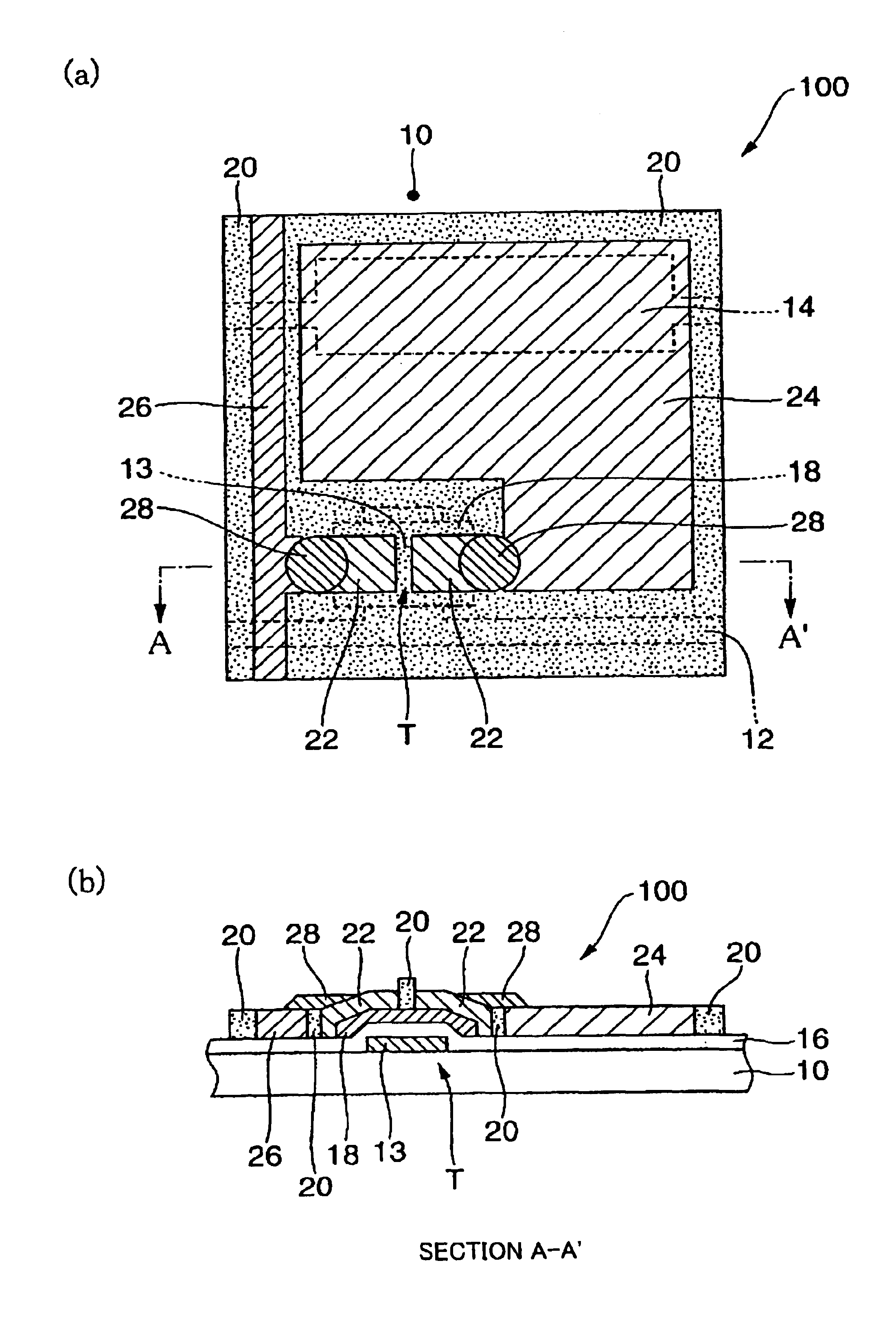
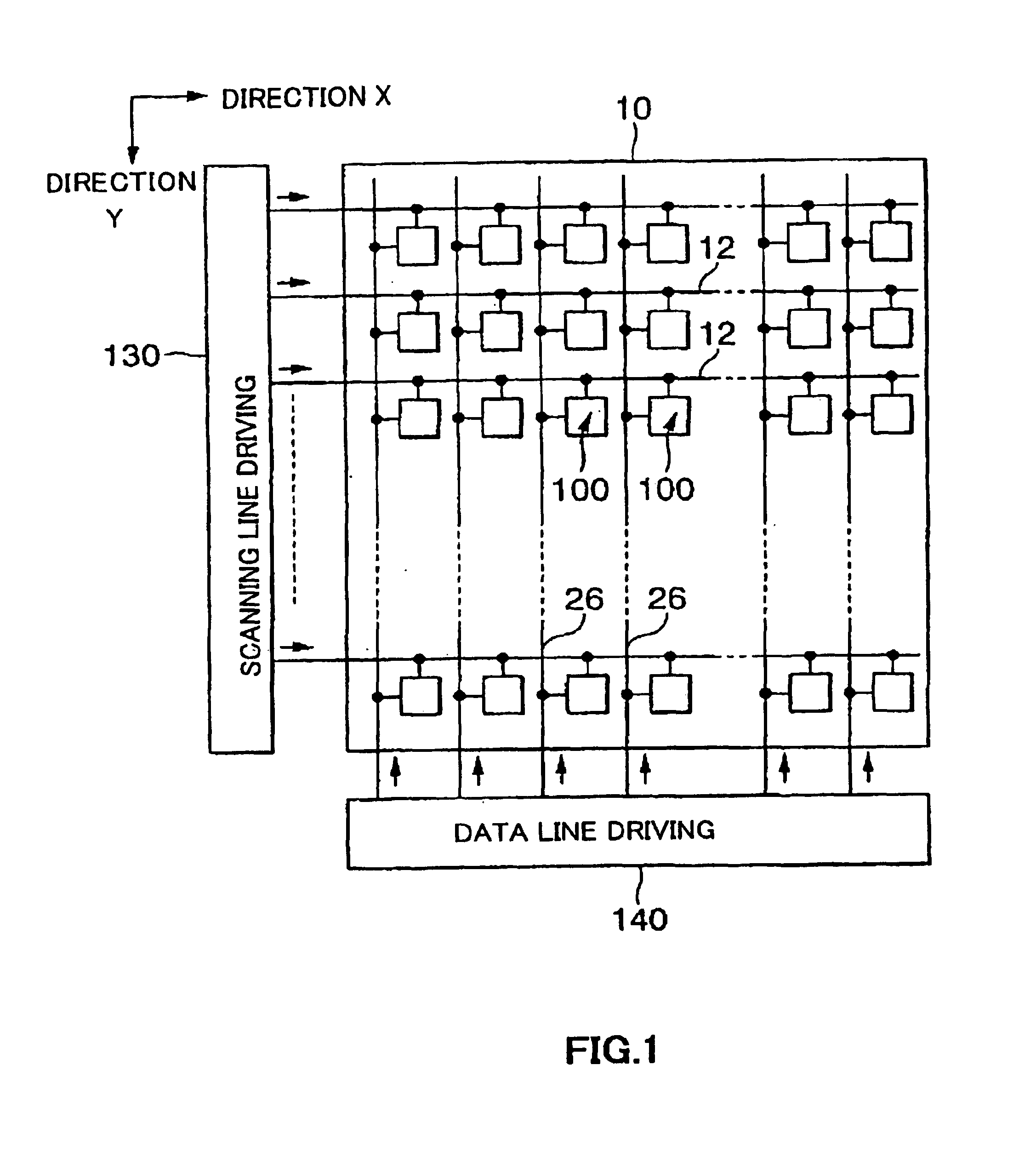
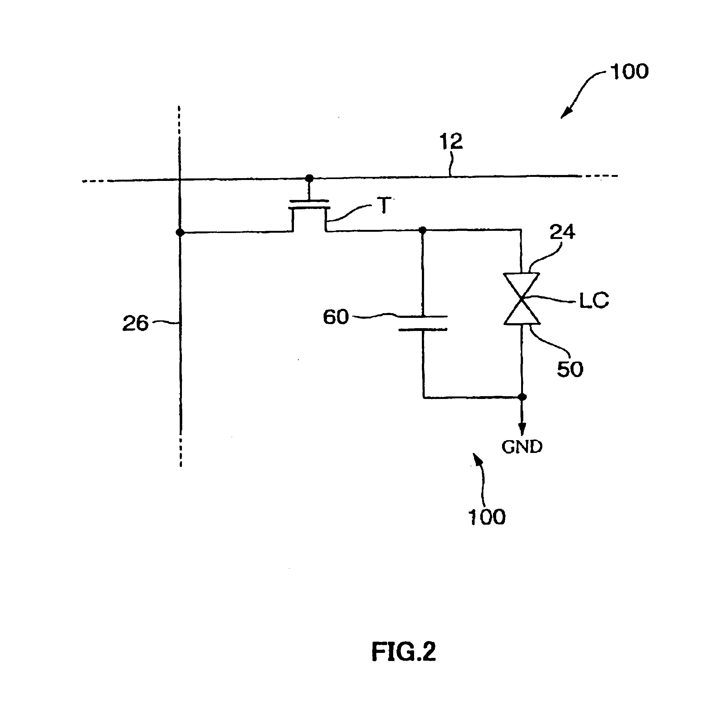
[0050]Now, a liquid crystal display device according to the first embodiment of the present invention and a method of manufacturing thereof will be described with reference to the appended drawings.

[0051]In the present invention, the droplet ejection method is the method of forming the desired pattern, including the ejected material, by ejecting droplets to a desired region and may be referred to as the inkjet method. In this case, the droplet to be ejected is not so-called ink used for printing but a liquid material containing materials constituting the device, the materials include materials serving as, for example, the conductive material or insulating material constituting the device. Further, the droplet ejection is not limited to ejection by atomization but includes continuous ejection of the liquid material drop by drop.

[0052]FIG. 1 schematically illustrates the configuration of the liquid crystal display device of this embodiment. The liquid crystal display device of this em...


PUM


Abstract

A pixel portion 100 of a liquid crystal display device includes a thin film transistor T including a gate electrode 13, a gate insulating film 16, a channel region 18, and source / drain regions 22, a source line (data) 26 for supplying current to the thin film transistor T and a pixel electrode 24. In the formation of a pixel circuit 100, a gate electrode 13, a gate insulating film 16, and the channel region 18 are firstly formed on a glass substrate 10. After the formation of the channel region 18 and the like, a polyimide film 20 surrounding the peripheries of the regions to be provide with the source / drain regions 22, the pixel electrode 24 and the source line 26 on a glass substrate 10 is formed. The regions surrounded with the wall of the polyimide film 20 are applied with a liquid material and subjected to a thermal treatment, thereby forming the element of the source / drain regions 22 and the like.

Description

BACKGROUND OF THE INVENTION[0001]1. Technical Field of the Invention[0002]The present invention relates to a method of manufacturing a device (for example, a semiconductor device) comprising thin film elements such as thin film transistors, and a device manufactured by the method.[0003]2. Description of the Related Art[0004]A liquid crystal display device has features of being thin, lightweight, and low power consuming, and thus it is used for various electronic apparatuses such as in personal computers, mobile phones, digital still cameras, or liquid crystal televisions.[0005]The liquid crystal display device is provided with pixel portions using thin film transistors. As the thin film transistor constituting the pixel portion, the inversely staggered type (or bottom gate type) structure constructed by forming a gate electrode on a substrate and laminating a semiconductor layer such as a channel region or a source / drain region or an insulating layer etc. thereon is being widely emp...

Claims


Application Information

Patent Timeline
IPC IPC(8): H01L21/70H01L21/84H01L27/12G02F1/1368H01L21/288H01L21/336H01L21/77H01L29/786
CPCH01L27/12H01L27/1292H01L27/1248
Inventor FURUSAWA, MASAHIRO
Owner SEIKO EPSON CORP
Learn More