
Cylinder valve insert

Inactive Publication Date: 2005-06-21
TAIWAN PAO
View PDF9 Cites 19 Cited by
  • Summary
  • Abstract
  • Description
  • Claims
  • Application Information

AI Technical Summary

Benefits of technology

[0011]In accordance with the present invention, a cylinder valve, such as, but not limited to, a LPG cylinder valve, includes a valve insert designed to reduce or prevent leakage of fluid from the cylinder valve when a fluid connector is connected to and / or disconnected from the cylinder valve. The valve insert can be removably or irremovably mounted in the cylinder valve. When the valve insert is removably mounted in the cylinder valve, the valve insert can be connected to the cylinder valve in a variety of manners such as, but not limited to, a threaded arrangement, a snap ring arrangement, a bolt or screw arrangement, a latch arrangement, and the like. When the valve insert is irremovably mounted in the cylinder valve, the valve insert can also be connected to the cylinder valve in a variety of manners such as, but not limited to, gluing, welding, brazing, soldering, riveting, and the like. Alternatively, the interior of the cylinder valve can be configured by molding, machining, or the like to integrally form one or more components of the valve insert in the cylinder valve.
[0015]The principal object of the present invention is to provide an insert for a cylinder valve which reduces the leakage or escape of gas when a fluid connector is connected to and / or disconnected from the cylinder valve.
[0016]Another objective of the present invention is to provide a valve insert that is simple to use and has a longer use-life then that of inserts heretofore available.
[0017]Still another objective of the present invention is to provide a valve insert that includes components that promote relative displacement with minimal wear therebetween.
[0018]A further object is the provision of a valve insert having an improved gas leakage sealing arrangement between relatively displaceable parts thereof and improved protection against the ingress of foreign matter to the area of the leakage sealing arrangement.

Problems solved by technology

In addition, gas escape or loss also occurs during the refilling of the gas vessel or cylinder.
However, these valve inserts still result in some gas escape or loss, especially after a male connector has been connected and disconnected several times from the gas vessel or cylinder.
Home '638 discloses that after repeated use of the Lechner valve insert, the strength of the spring may weaken, resulting in the POL nipple not hermetically engaging the docking member prior to the seal moving to an opened position.
However, after repeated connection and disconnection of the nipple from the valve member, the movement of the valve member in the tubular member of the valve insert can become impaired.
The seals between the valve member and the tubular member can become worn thereby impairing the movement of the valve member in the tubular member.
This impaired movement can cause the valve member to stick in the opened position and / or cause the seal between the nipple and the docking member to be prematurely compromised when the nipple is withdrawn from the valve member, thereby causing a gas leak.
This wiping of the lubricant results in the valve member being susceptible to sticking in these wiped regions.
Dirt and other foreign material can also impair the movement of the valve member in the tubular member by becoming wedged between the valve member and tubular member.

Method used


Image

  • Cylinder valve insert
  • Cylinder valve insert
  • Cylinder valve insert

Examples


Embodiment Construction

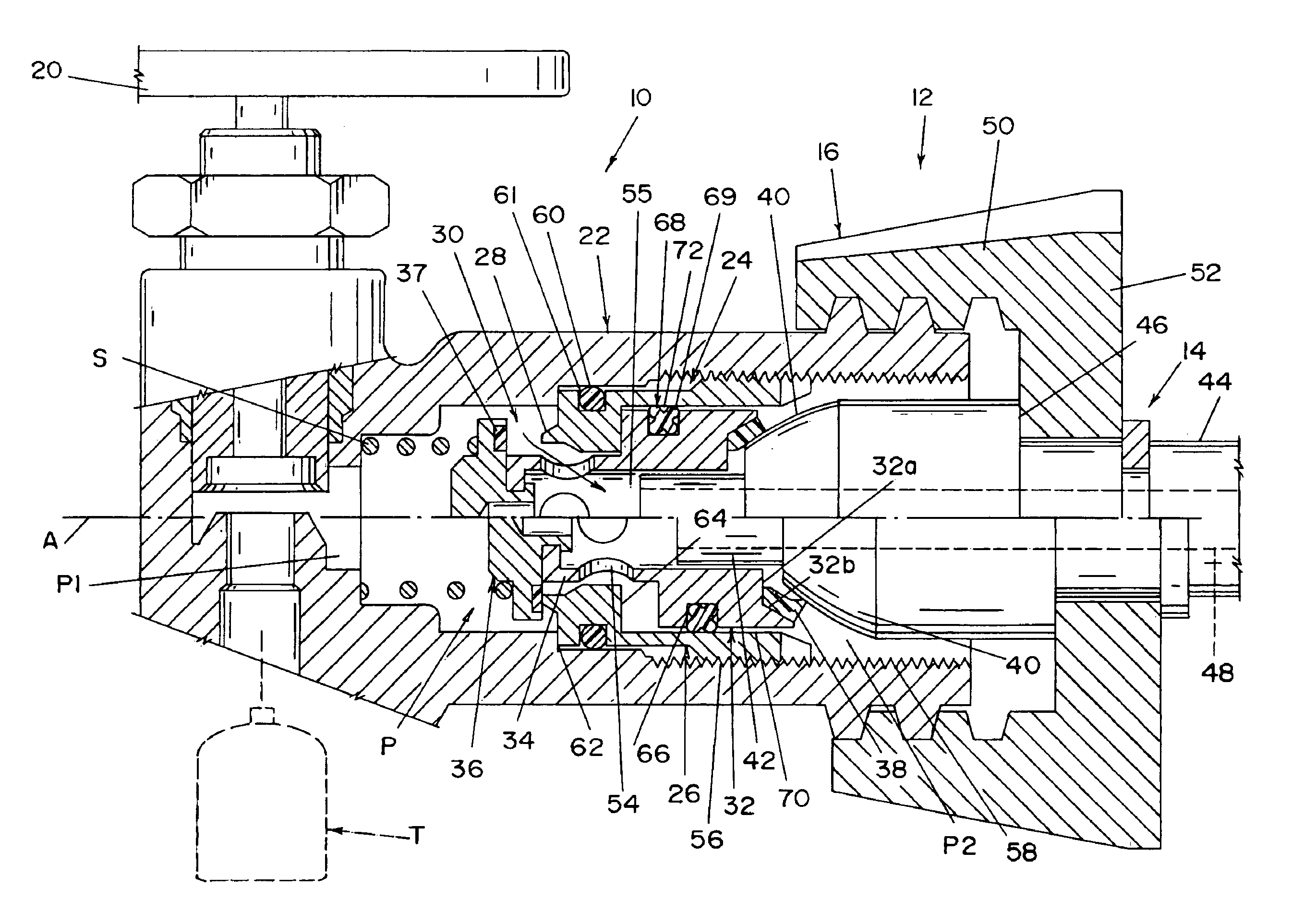
[0025]Referring now in greater detail to the drawings, wherein the showings are for the purpose of illustrating the preferred embodiments of the invention only and not for the purpose of limiting the invention, FIG. 1 illustrates an arrangement for connecting an LPG tank T with a gas consuming appliance such as a propane gas grill, not shown, and which arrangement comprises a cylinder valve 10 mounted on tank T, and a coupling 12 for connecting valve 10 with the appliance. Coupling 12 comprises a nipple 14 and a coupling nut 16. As is well known, valve 10 includes a primary shutoff valve element 18 operable through a knob or handle 20 to open and close valve 10 to the flow of gas from tank T through a passageway P defined by a conduit portion 22 of valve 10. Passageway P has an axis A, an upstream end P1 for receiving gas from tank T when valve 18 is open, and a downstream end P2 for delivering gas to the appliance. As is further well known, conduit 22 receives and supports a valve ...


PUM


Abstract

A valve insert for a cylinder valve for connecting an LPG tank to a gas consuming appliance has a body member mounted in the outlet end of the cylinder valve and a valve element slidable in the body member and cooperable therewith to control the flow of gas from the tank to the appliance. A quad sealing ring between the valve body and valve element seals against gas leakage therebetween and provides a lubricant reservoir for lubricating the surfaces thereof, and a wiper ring downstream of the quad sealing ring cleans the surfaces and precludes the ingress of foreign matter to the area of the gas sealing quad ring.

Description

[0001]The present invention is related to the field of valves for household and recreational vehicle use and, more particularly, to an improved valve insert which is adapted to be mounted to the outlet end of an LPG cylinder valve to improve sealing with a separable male fitting. The present invention claims priority based on U.S. Provisional Patent Application Ser. No. 60 / 397,013 filed Jul. 22, 2002.BACKGROUND OF THE INVENTION[0002]Gaseous fuels, such as butane and propane, have found a wide acceptance in household and recreational vehicle use. Such fuels are commonly used in association with gas grills, gas lamps, gas heaters, gas cutting torches, and other similar devices. When using such devices, an individual obtains a pressurized gas vessel or cylinder and then connects the vessel or cylinder to a gas consuming device. Typically, the gas consuming device operates at a pressure less than the gas pressure in the pressurized gas vessel or cylinder. As a result, a pressure regulat...

Claims


Application Information

Patent Timeline
IPC IPC(8): F16L37/28F16L37/42
CPCF16L37/42F17C2205/037Y10T137/4273
Inventor BARTOS, JOSEF A.GREWAL, HARSHARAN
Owner TAIWAN PAO
Learn More