
Abnormality detecting device for vehicular hydraulic pressure control circuit

Inactive Publication Date: 2005-06-21
TOYOTA JIDOSHA KK
View PDF7 Cites 21 Cited by
  • Summary
  • Abstract
  • Description
  • Claims
  • Application Information

AI Technical Summary

Benefits of technology

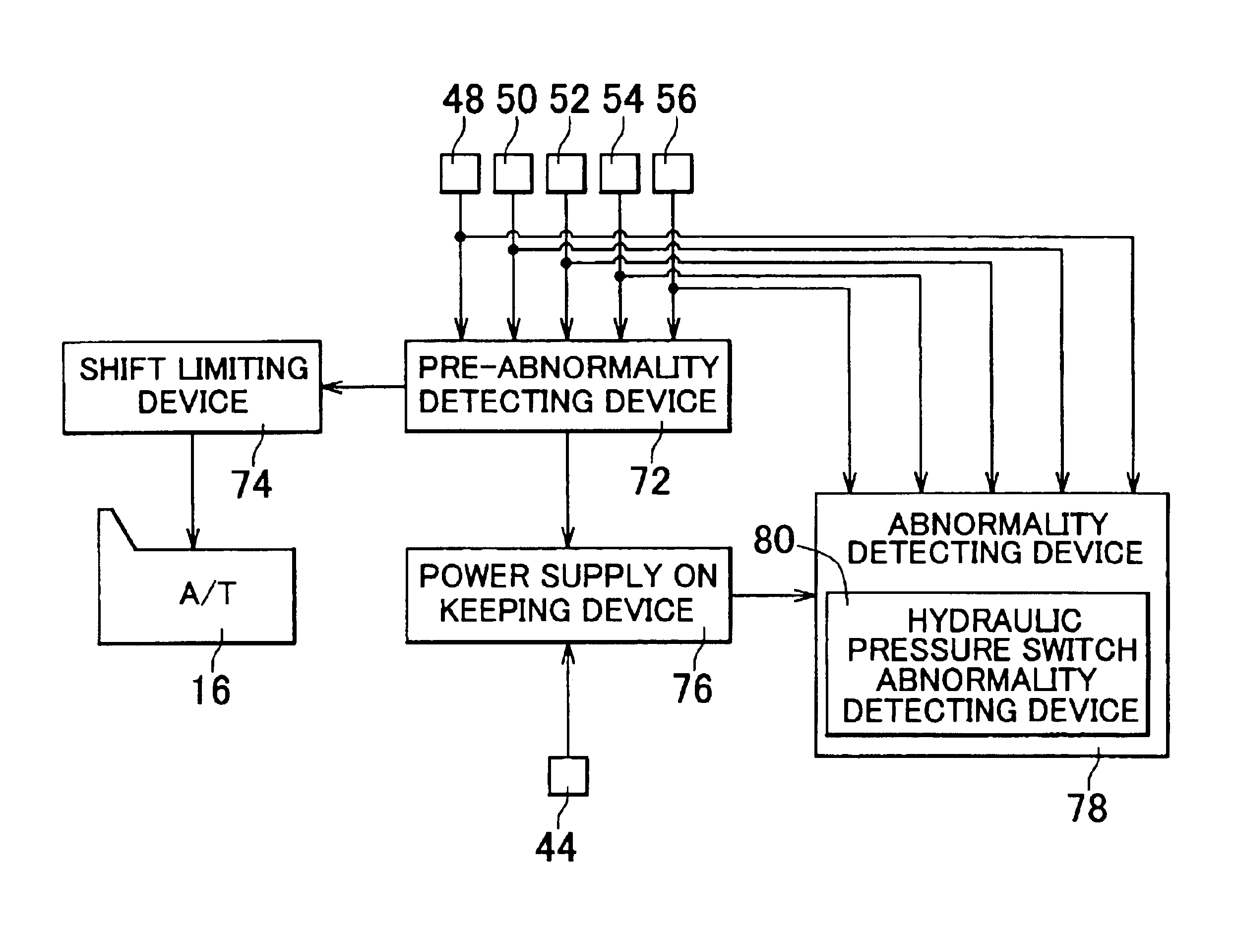
[0009]With the above-mentioned abnormality detecting device and abnormality detecting method, the power supply of the electronic control unit is kept ON for the predetermined time after the ignition switch is turned from ON to OFF, and an abnormality which has occurred in the hydraulic pressure control circuit is detected within the predetermined time. Accordingly, it is possible to compare the state in which the hydraulic pressure can be generated from the electromagnetic control valve with the state in which the hydraulic pressure cannot be generated from the electromagnetic control valve. As a result, it is possible to determine whether an abnormality has occurred in the hydraulic switch or in an element other than the hydraulic switch, such as the electromagnetic control valve. Namely, it is possible to reliably detect an abnormality which has occurred in the vehicular hydraulic pressure control circuit.

Problems solved by technology

However, when an abnormality occurs in the plurality of the electromagnetic control valves, the automatic transmission might operate irregularly.
However, in the conventional technology, when it is determined that the hydraulic switch is ON in the state where the hydraulic pressure should not be supplied, it is impossible to determine whether the hydraulic pressure is output due to an abnormality in the electromagnetic control valve, or there is an abnormality in the hydraulic switch.

Method used


Image

  • Abnormality detecting device for vehicular hydraulic pressure control circuit
  • Abnormality detecting device for vehicular hydraulic pressure control circuit
  • Abnormality detecting device for vehicular hydraulic pressure control circuit

Examples


Embodiment Construction

[0018]In the following description and the accompanying drawings, the present invention will be described in more detail with reference to exemplary embodiments.

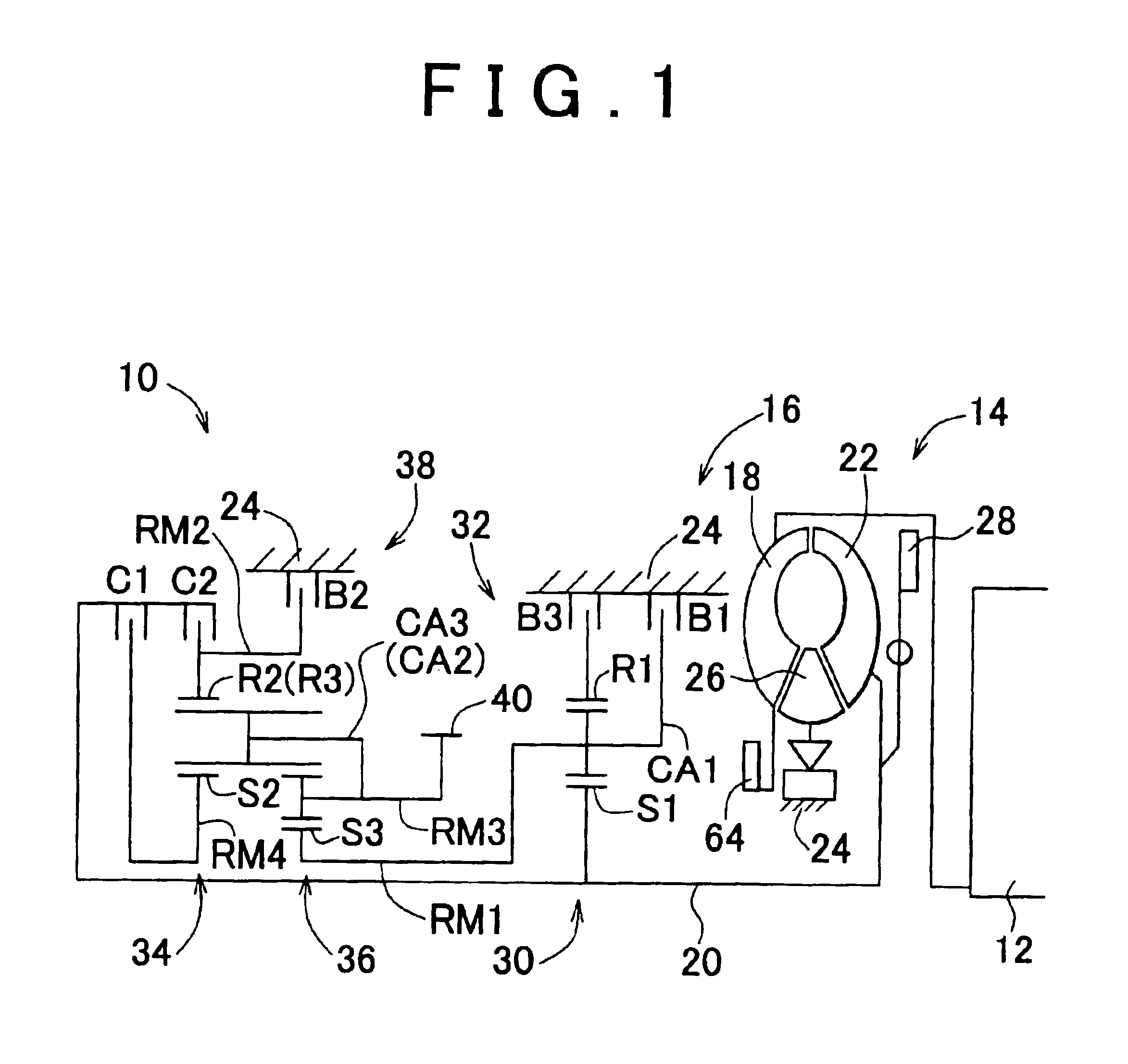
[0019]FIG. 1 is a view schematically showing a power transmission device 10 to which an abnormality detecting device for a vehicular hydraulic pressure control circuit, according to an embodiment of the invention, is applied. The power transmission device 10 includes an automatic transmission 16 of a transverse type, and is appropriately applied to a FF (front engine front drive) vehicle. In the power transmission device 10, driving force generated by an engine 12, which is a driving power source for running, is transmitted to right and left wheels via a torque converter 14, the automatic transmission 16, a differential gear unit (not shown), and a pair of axles.

[0020]The engine 12 is an internal combustion engine, e.g. a gasoline engine, which generates driving force by combustion of fuel that is injected into cylinders. Th...


PUM


Abstract

In an abnormality detecting device and method for a vehicular hydraulic pressure control circuit, which determines an abnormality that has occurred in a hydraulic pressure control circuit including an electromagnetic control valve which generates hydraulic pressure corresponding to a signal supplied from an electronic control unit, and a hydraulic switch which is turned ON when the hydraulic pressure generated by the electromagnetic control valve is equal to or higher than a predetermined value, a power supply of the electronic control unit is kept ON for a predetermined time after an ignition switch is turned from ON to OFF, and an abnormality that has occurred in the hydraulic pressure control circuit is detected within the predetermined time. Thus, it is possible to reliably detect an abnormality that has occurred in the vehicular hydraulic pressure control circuit.

Description

INCORPORATION BY REFERENCE[0001]The disclosure of Japanese Patent Application No. 2003-137842 filed on May 15, 2003, including the specification, drawings and abstract is incorporated herein by reference in its entirety.BACKGROUND OF THE INVENTION[0002]1. Field of the Invention[0003]The invention relates refinement in an abnormality detecting device for detecting an abnormality which has occurred in a vehicular hydraulic pressure control circuit.[0004]2. Description of the Related Art[0005]Generally, an automatic transmission for a vehicle is controlled by engaging / applying or disengaging / releasing a plurality of hydraulic friction engaging devices included in the automatic transmission, using operating oil which is supplied from a predetermined hydraulic pressure control circuit. In recent years, an automatic transmission, in which each of the plurality of the hydraulic friction engaging devices is controlled by a dedicated electromagnetic control valve, is widely used. With such a...

Claims


Application Information

Patent Timeline
IPC IPC(8): F16H61/12F16H59/68F16H59/74F16H61/68F16H61/684F16H61/686
CPCF16H61/12F16H59/68F16H61/686F16H2061/1208F16H2061/0209F16H2059/683F16H2061/1264F16H2061/1284Y10S477/906F16H2061/1224E06B1/58E06B1/6069
Inventor SUGIMURA, TOSHIO
Owner TOYOTA JIDOSHA KK
Learn More