
Eddy current inspection method

a technology of eddy current and inspection method, which is applied in the direction of mechanical measurement arrangement, mechanical roughness/irregularity measurement, instruments, etc., can solve the problems of material introduction, material defect, or other anomalies, and disturb the eddy current,

Active Publication Date: 2005-06-14
GENERAL ELECTRIC CO
View PDF5 Cites 23 Cited by
  • Summary
  • Abstract
  • Description
  • Claims
  • Application Information

AI Technical Summary

Benefits of technology

[0017]Accordingly, it is desired to provide an improved method of eddy current in

Problems solved by technology

The rotating components are subject to substantial centrifugal loads during operation which generate corresponding stress that must be limited for maximizing component life.
However, defects, flaws, or other anomalies in the material may be introduced during the original manufacture of the engine components, or may occur during the operational life thereof.
A defect or geometric abnormality in the material which changes the homogeneity thereof will disturb the eddy current.
Crack detection is particularly important in turbine engine components since cracks may propagate under stress and substantially reduce the useful life of a component, and may eventually lead to component failure if not suitably accommodated.
Correspondingly, the small coil is very sensitive to the operating environment of the inspection equipment.
However, since the target region of a typical specimen has a changing contour subject manufacturing tolerances it is quite difficult to accurately align the probe and automate the inspection process.
Alignment of the probe and component specimen has been a complex and lengthy process in which a specifically configured template is required.

Method used


Image

  • Eddy current inspection method
  • Eddy current inspection method
  • Eddy current inspection method

Examples


Embodiment Construction

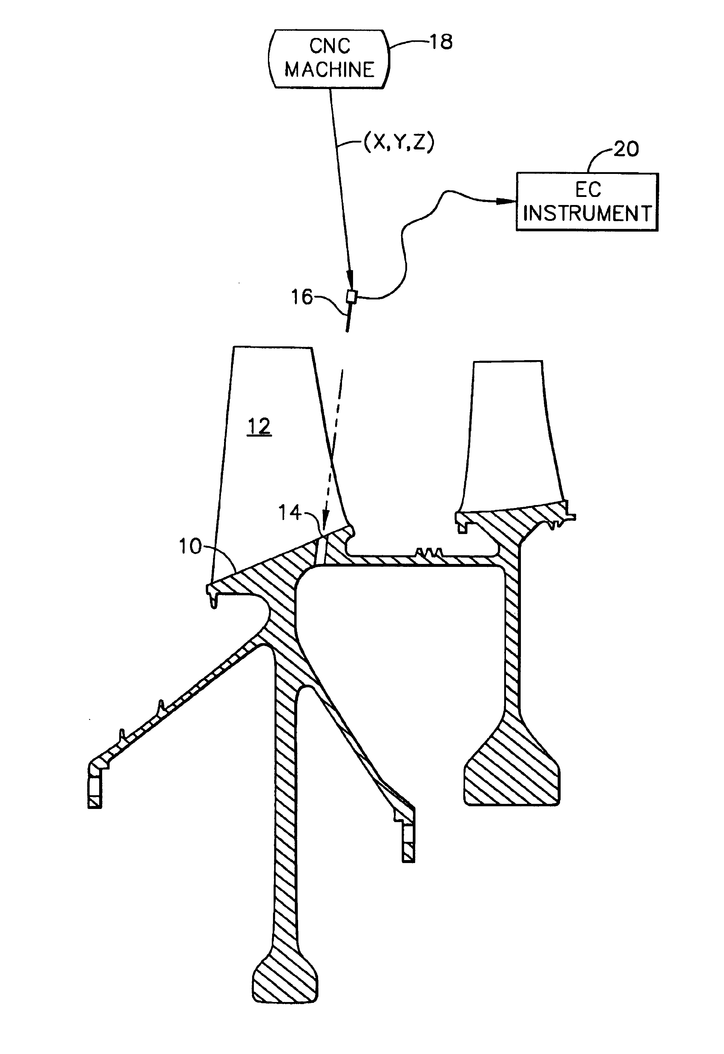
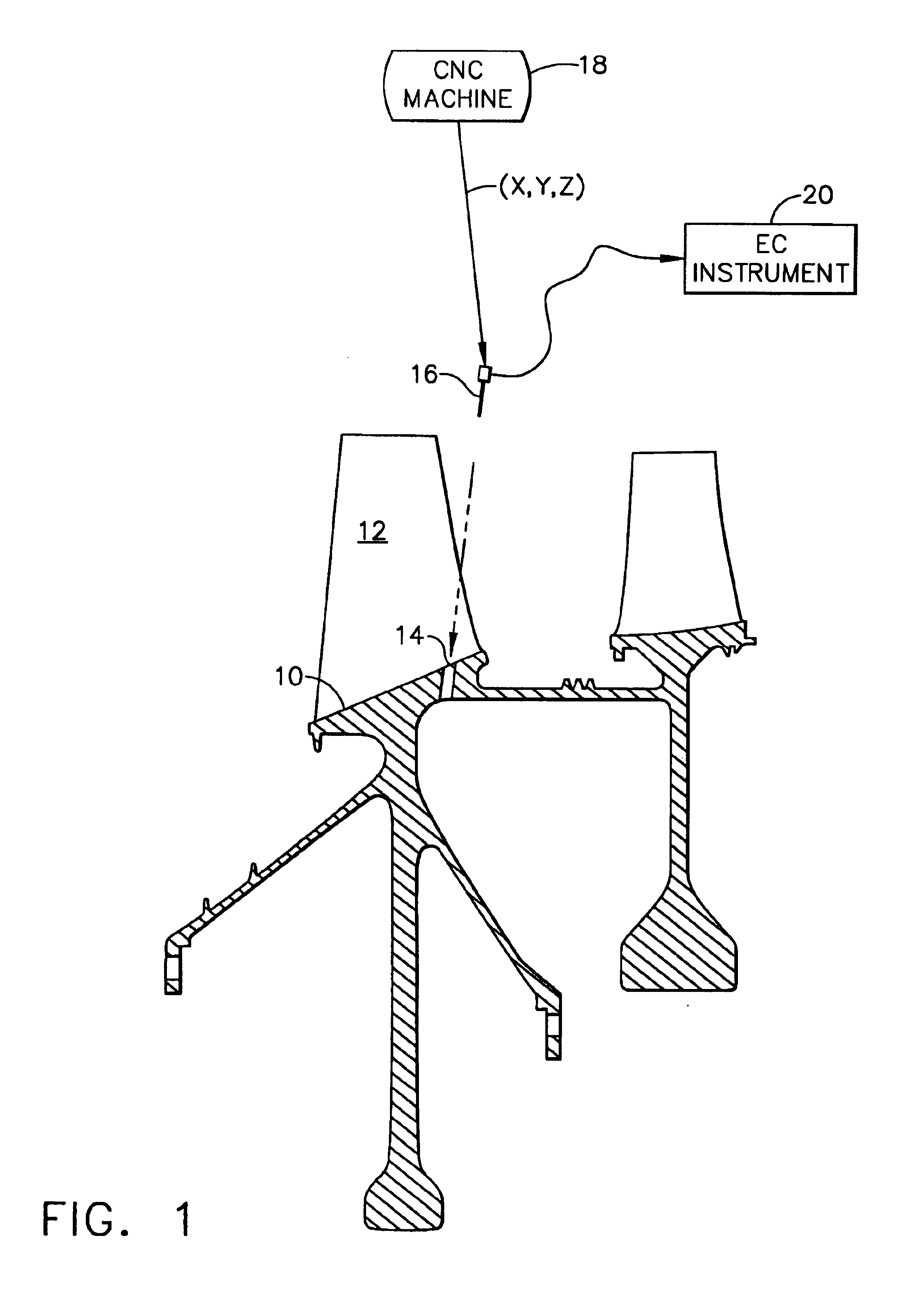
[0024]Illustrated in FIG. 1 is a specimen 10 in the exemplary form of a compressor rotor disk for a gas turbine engine. The disk specimen includes an annular rim from which extend radially outwardly a row of compressor rotor blades 12, which are integrally formed therewith in a unitary blisk configuration in this exemplary embodiment. This embodiment also includes a second blisk in a tandem configuration with the first blisk, although any component of the engine or other apparatus may be used as a specimen.

[0025]The entire specimen is subject to centrifugal loading during operation in the gas turbine engine and therefore develops centrifugal stress therein. In the exemplary embodiment illustrated in FIG. 1, the specimen includes a local target 14 in the form of a radial oil drain hole extending completely through the rim of the disk specimen between two of the compressor blades.

[0026]Eddy current (EC) inspection of the specimen target may be automated by mounting the specimen 10 and...


PUM


Abstract

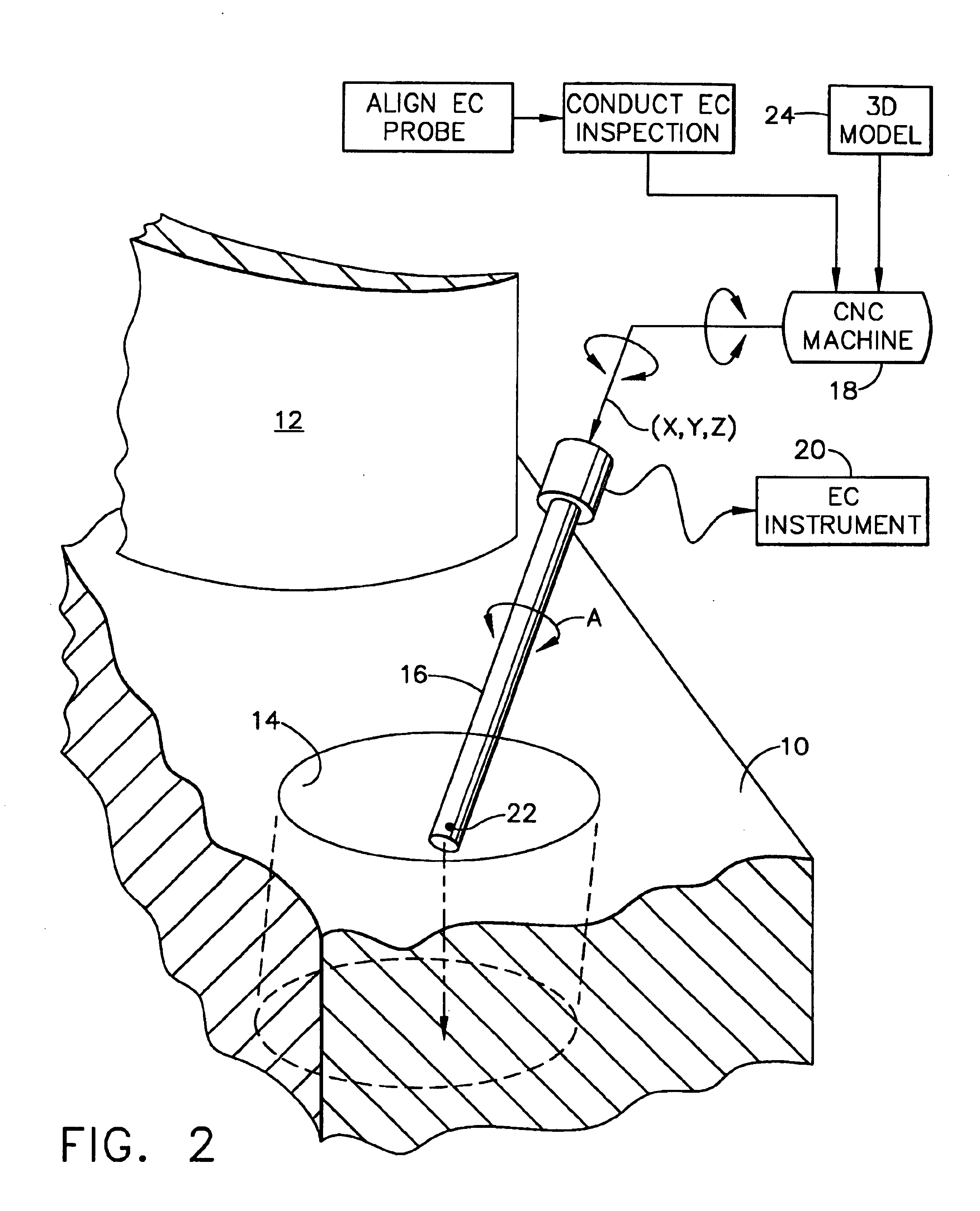
A specimen is mounted in a multiaxis machine. An eddy current probe is also mounted in the machine for multiaxis movement relative to the specimen. The probe is aligned in situ with a target in the specimen by direct contact therebetween at multiple alignment sites corresponding with a numerical model of the specimen. Eddy current inspection of the target may then be conducted by moving the probe along multiple inspection sites of the target corresponding with the specimen model.

Description

BACKGROUND OF THE INVENTION[0001]The present invention relates generally to non-destructive testing, and, more specifically, to eddy current inspection.[0002]Gas turbine engines include rotating shafts and disks which support rotating blades in the fan, compressor, high pressure turbine, and low pressure turbine. Commercial and military turbine engines used for powering aircraft in flight require minimum weight while still ensuring a suitable useful life of the engine components.[0003]The rotating components are subject to substantial centrifugal loads during operation which generate corresponding stress that must be limited for maximizing component life. Various forms of superalloy materials are commonly used in modern aircraft turbine engines for ensuring component integrity over the useful life thereof.[0004]However, defects, flaws, or other anomalies in the material may be introduced during the original manufacture of the engine components, or may occur during the operational li...

Claims


Application Information

Patent Timeline
IPC IPC(8): G01N27/90G01B7/28
CPCG01N27/902G01B7/285
Inventor SUH, UI WONSNEED, JR., CLIFFORD
Owner GENERAL ELECTRIC CO
Learn More