
Mass spectrometer

a mass spectrometer and mass spectrometer technology, applied in mass spectrometers, isotope separation, particle separator tubes, etc., can solve the problems of increasing the discriminator level, unparallel speed, and the limiting factor for protein identification is not the quality of ms/ms, so as to improve sensitivity, increase the delay time of the pusher electrode, and improve the effect of sensitivity

Inactive Publication Date: 2005-06-14
MICROMASS UK LTD
View PDF33 Cites 146 Cited by
  • Summary
  • Abstract
  • Description
  • Claims
  • Application Information

AI Technical Summary

Benefits of technology

This approach significantly improves the sensitivity and efficiency of protein identification by selectively isolating desired charge states, allowing for a near 100% duty cycle and reducing background noise, enabling the detection of ions across the whole mass range with high accuracy.

Problems solved by technology

Mass spectrometry has firmly established itself as the primary technique for identifying proteins due to its unparalleled speed, sensitivity and specificity.
However, often the limiting factor for identification of the protein is not the quality of the MS / MS spectrum produced but is the initial discovery of the multiply charged peptide precursor ion in the MS mode.
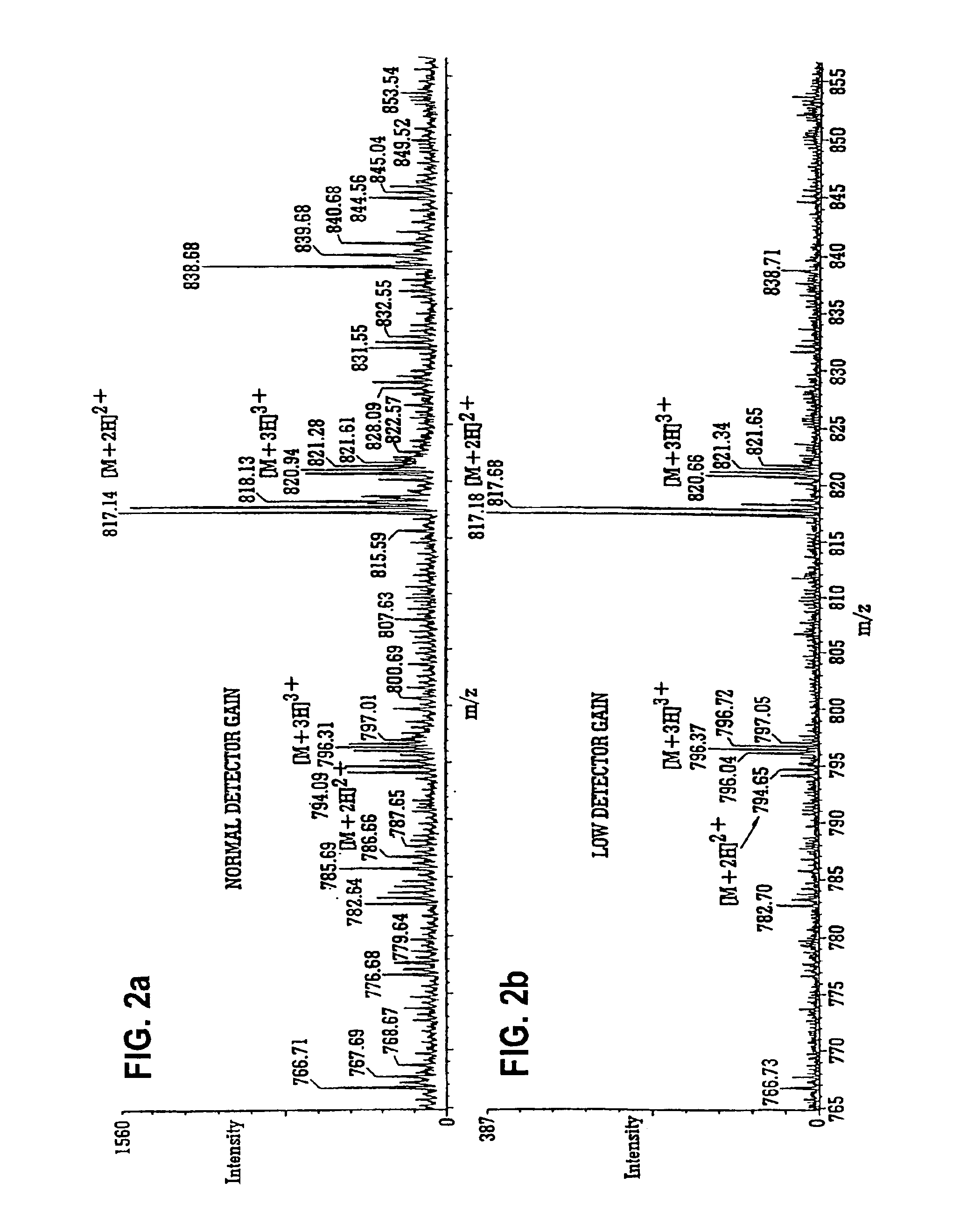
An important disadvantage of lowering the detector gain (or of increasing the discriminator level) is that the sensitivity is lowered.
Using this method it is also impossible to pick out an individual charge state.
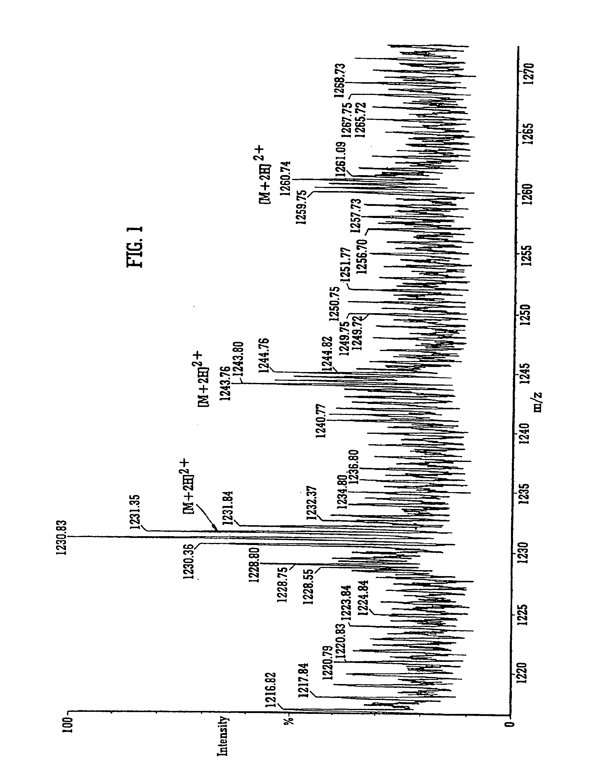
When a MALDI ion source is used high levels of singly charged matrix related ions and chemical noise are generated which make it difficult to identify candidate peptide ions.

Method used


Image

  • Mass spectrometer
  • Mass spectrometer
  • Mass spectrometer

Examples


Embodiment Construction

[0130]Various embodiments of the present invention will now be described. FIG. 3 shows the relationship of flight time in a drift region of a time of flight mass analyser versus drift time in an ion mobility spectrometer for various singly and doubly charged ions. An experimentally determined relationship between the mass to charge ratio of ions and their drift time through an ion mobility spectrometer is shown in FIG. 4. This relationship can be represented by an empirically derived polynomial expression. As can be seen from these figures, a doubly charged ion having the same mass to charge ratio as a singly charged ion will take less time to drift through an ion mobility spectrometer compared with a singly charged ion. Although the ordinate axis of FIG. 3 is given as the flight time through the drift region of a time of flight mass analyser, it will be appreciated that this correlates directly with the mass to charge ratio of the ion.

[0131]If a mass filter is provided in combinati...


PUM


Abstract

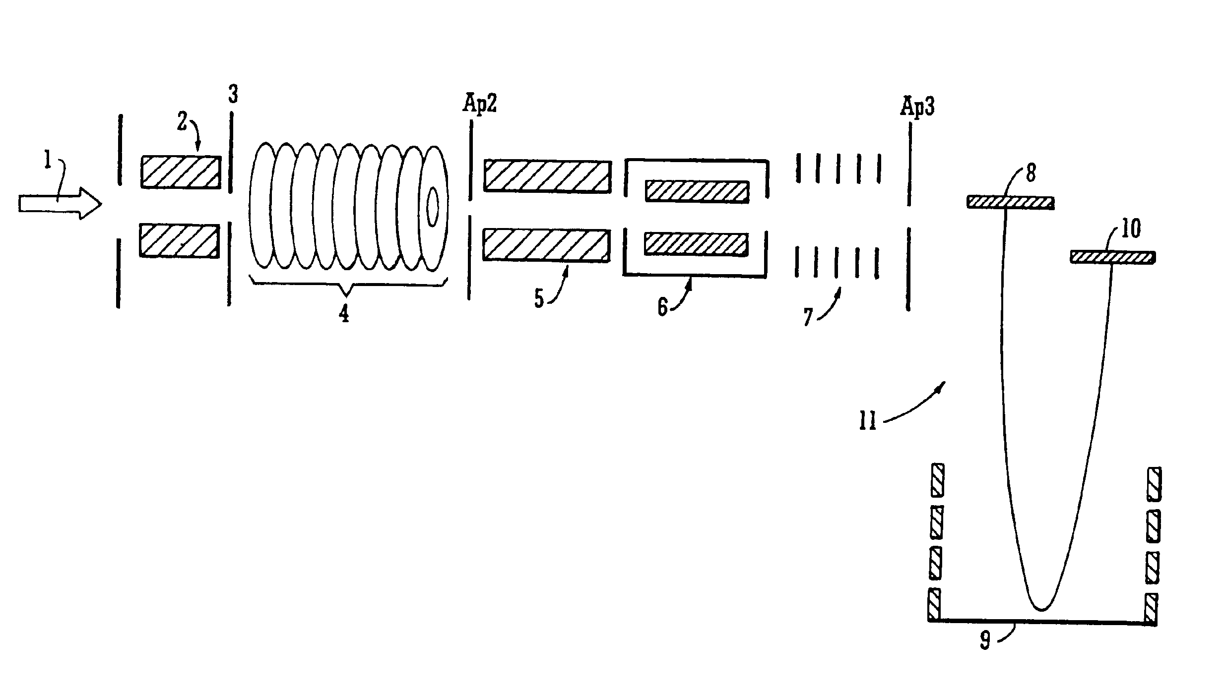
A mass spectrometer is disclosed wherein ions having a particular desired charge state are selected by operating an ion mobility spectrometer in combination with a quadrupole mass filter. Precursor ions are fragmented or reacted to form product ions in a collision cell ion trap and sent back upstream to an upstream ion trap. The fragment or product ions are then passed through the ion mobility spectrometer wherein they become temporally separated according to their ion mobility. Fragment or product ions are then re-trapped in the collision cell ion trap before being released therefrom in packets. A pusher electrode of a time of flight mass analyzer is energized a predetermined period of time after a packet of ions is released from the collision cell ion trap. Accordingly, it is possible to select multiply charged precursor ions from a background of singly charged ions, fragment them, and mass analyze the fragment ions with a near 100% duty cycle across the whole mass range.

Description

CROSS-REFERENCE TO RELATED APPLICATIONS[0001]The present application constitutes a continuation-in-part of U.S. patent application Ser. No. 10 / 176,072 filed Jun. 21, 2002, pending.BACKGROUND OF THE INVENTION[0002]1. Field of the Invention[0003]The present invention relates to mass spectrometers.[0004]2. Discussion of the Prior Art[0005]With the decoding of the 20-30,000 genes that compose the human genome, emphasis has switched to the identification of the translated gene products that comprise the proteome. Mass spectrometry has firmly established itself as the primary technique for identifying proteins due to its unparalleled speed, sensitivity and specificity. Strategies can involve either analysis of the intact protein, or more commonly digestion of the protein using a specific protease that cleaves at predictable residues along the peptide backbone. This provides smaller stretches of peptide sequence that are more amenable to analysis via mass spectrometry.[0006]The mass spectr...

Claims


Application Information

Patent Timeline
Patent Type & Authority Patents(United States)
IPC IPC(8): H01J49/34H01J49/10H01J49/40H01J49/16H01J49/42
CPCH01J49/004H01J49/429H01J49/42H01J49/401
Inventor HOYES, JOHN BRIAN
Owner MICROMASS UK LTD
Learn More