
Vehicular lamp

a technology of a lamp and a lamp body is applied in the field of a lamp body, which can solve the problems of poor external appearance of the lamp body

Inactive Publication Date: 2005-06-14
KOITO MFG CO LTD
View PDF4 Cites 5 Cited by
  • Summary
  • Abstract
  • Description
  • Claims
  • Application Information

AI Technical Summary

Benefits of technology

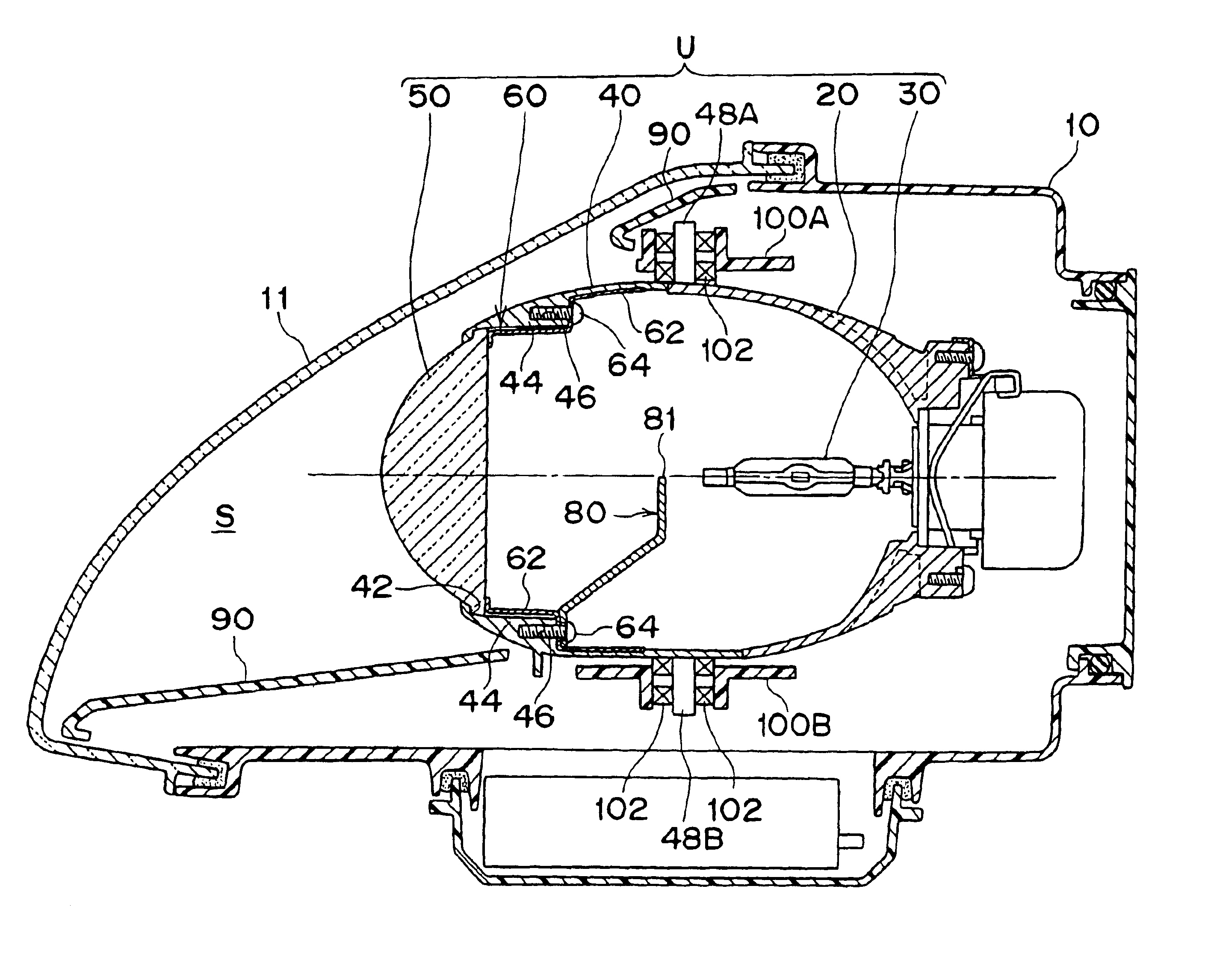
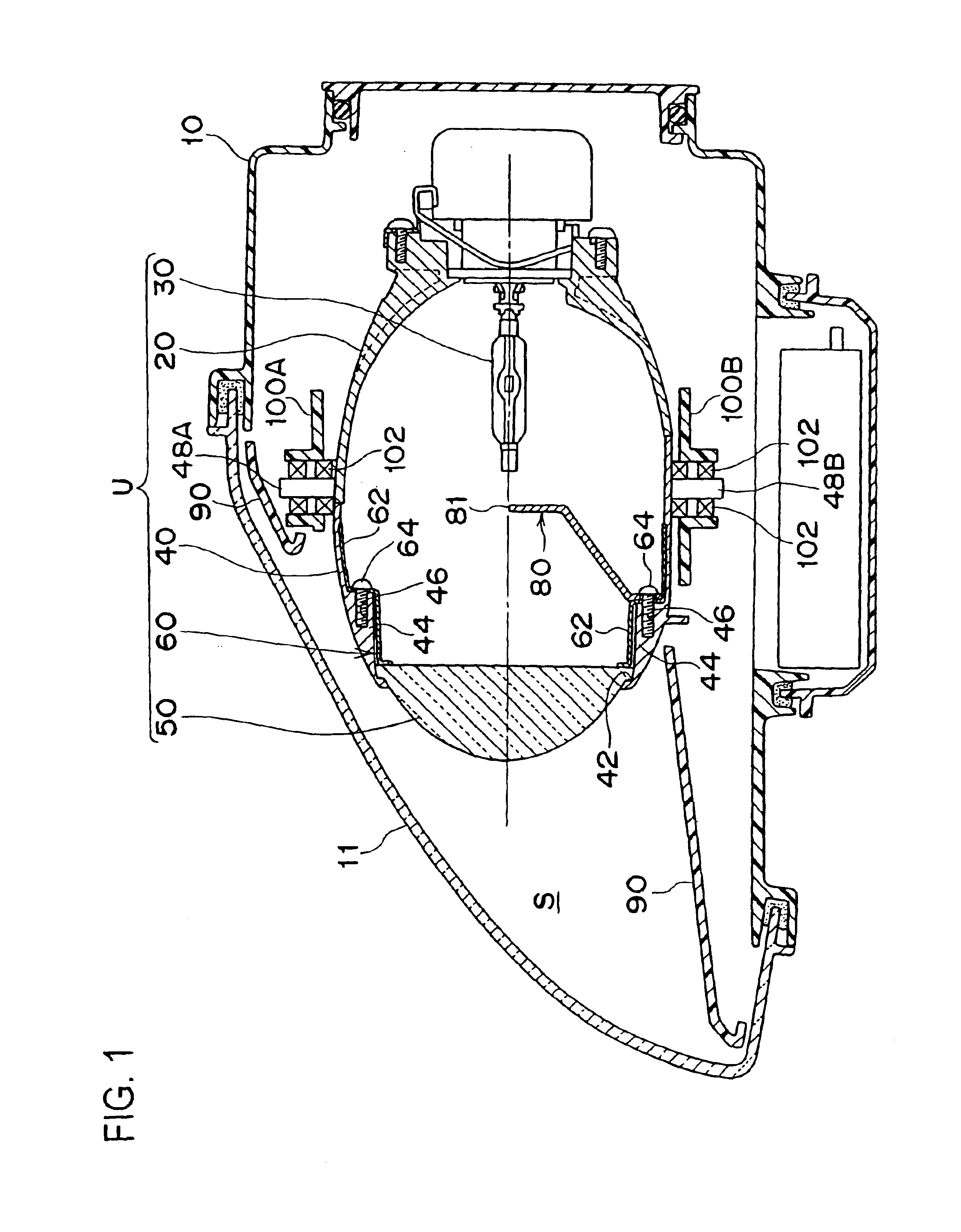
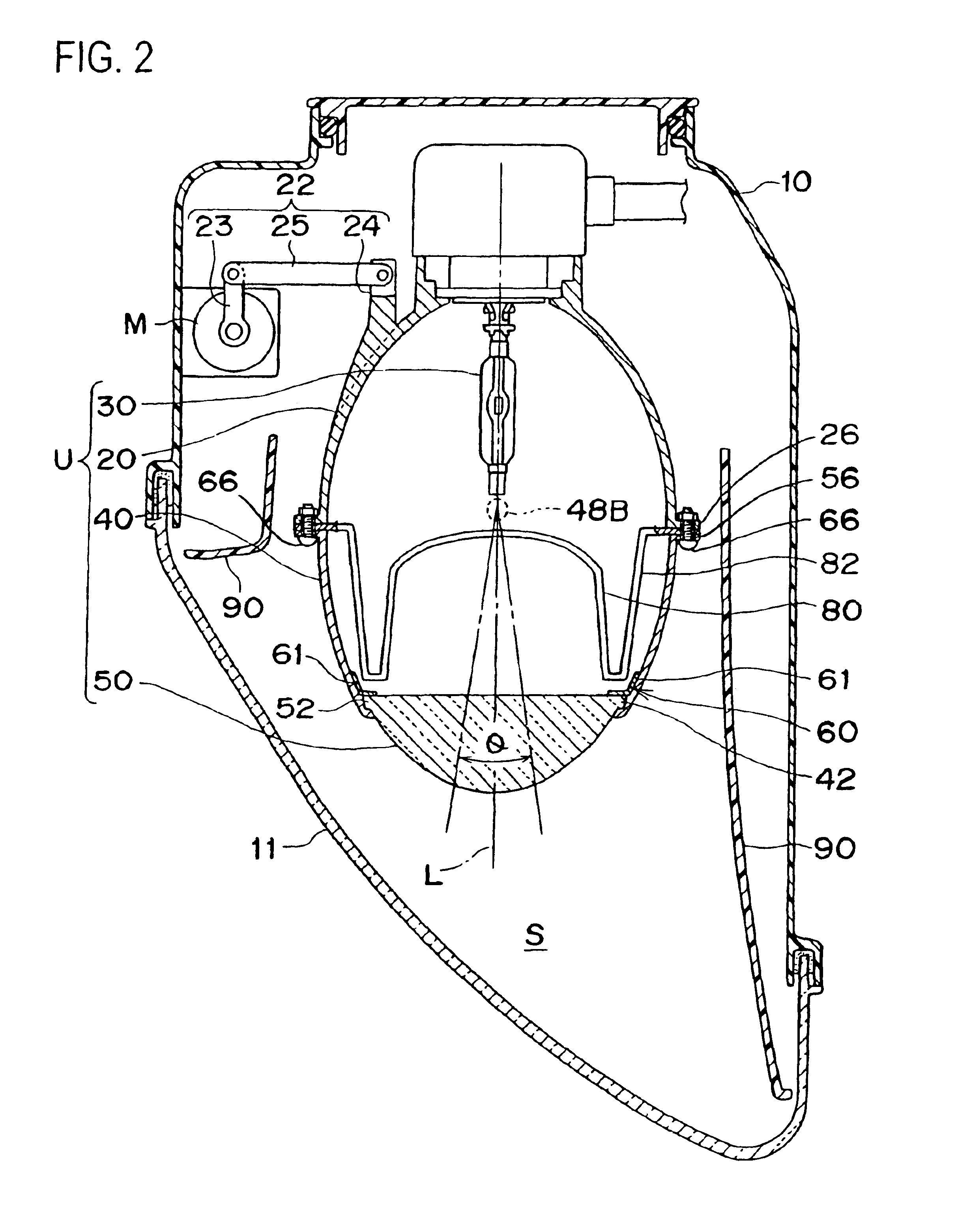
[0007]It is an object of the present invention to provide a vehicular lamp having an improved appearance when it is not lit by providing a lens fixing means in the lens holder so that the lens fixing means is prevented from being exposed to the outside of a projection-type light source unit.
[0011]In this structure, the means that fixes the convex lens can be screw fixing, spring (elastic) fixing, caulk fixing, concavo-convex engagement fixing, and the like. When the convex lens is made of glass and fitted by screws to the lens holder made of a metal, the peripheral portion of the convex lens is fixed by screws with a metallic lens fitting, which is a holding member, interposed in between. This structure allows the convex lens to be secured without getting any damage and without getting loosened. Furthermore, when the convex lens is fixed by spring fixing or caulking fixing, the peripheral portion of the convex lens is fixed to the lens engaging portion by an elastic member such as a heat resistant rubber or a wavy washer. When concavo-convex engagement fixing is employed, the peripheral portion of the convex lens is engaged with the lens engaging portion in a concavo-convex fitting by way of covering the peripheral portion of the convex lens with an elastic member such as a heat resistant rubber that has a U-shaped cross-section.
[0018]The toric lens fitting makes a tight contact with the inner surface of the lens holder, and it does not protrude to the light path and thus does not prevent the formation of light distribution.
[0019]In addition, the toric lens fitting, by functioning in corporation with the ring-shaped inner flange portion, sandwiches the peripheral portion of the convex lens, so that it securely holds the convex lens to the lens holder without looseness.
[0020]Furthermore, the peripheral portion of the convex lens can be securely held easily by the lens engaging portion by imposing the lens fitting and by screwing the fastening screws to the screw holes formed in the bosses.

Problems solved by technology

Thus, the problem of this lamp is that its external appearance is poor.

Method used


Image

  • Vehicular lamp
  • Vehicular lamp
  • Vehicular lamp

Examples


second embodiment

[0049]FIG. 4 shows a spring (elastic) fixing structure that secures the convex lens in the front edge of the lens holder, the main portion of the present invention.

[0050]In this second embodiment, an elastic member 48 is used. The elastic member 48 has a U-shaped transverse section (appearing in a reversed U-shape in FIG. 4) and is comprised of a heat resistant rubber or the like. The elastic member 48 covers the entire outer peripheral surface of the peripheral portion 52 of the convex lens 50. Te peripheral portion 52 of the convex lens 50 is thus supported by the lens engaging portion 42 and the lens fitting 60.

[0051]Dimensional errors that occurred in the manufacturing process of (the peripheral portion 52 of) the convex lens 50, the lens engaging portion 42, and (the leg 82 of) the shade 80 that forms a clear cut line are absorbed by the elastic member 48. As a result, the convex lens 50 and the shade 80 that forms a clear cut line can be fixed to the lens holder 40 without get...

third embodiment

[0053]FIG. 5 shows another structure for installing the convex lens in the front edge of the lens holder, the main portion of the present invention.

[0054]In the first and second embodiments, the lens fixing means for fixing the convex lens 50 to the front edge of the lens holder 40 is comprised of the fastening screws 64, the bosses 44 having the screw holes and the lens fitting 60. However, in this third embodiment shown in FIG. 5, the lens fixing means is caulking.

[0055]More specifically, a caulking member 110 of a toric shape is loaded so as to contact the peripheral portion 52 of the convex lens 50 which is to be engaged with the lens engaging portion 42. Thus, with the plastic deformation force of the caulking member 110 in the outward direction or in the radial direction as shown by arrow in FIG. 5, the caulking member 110 is stuck to the lens engaging portion 42; and in this way, the peripheral portion 52 of the convex lens 50 is securely held to the lens engaging portion 42....

fourth embodiment

[0056]FIG. 6 shows still another structure for installing the convex lens in the front edge of the lens holder, the main portion of the present invention.

[0057]In this forth embodiment, the lens fixing means is comprised of a C-ring 120. In other words, the toric C-ring 120 is provided so as to contact the peripheral portion 52 of the convex lens 50 and to be engaged with the lens engaging portion 42, and it is pressed against the inner peripheral wall 42a of the lens engaging portion 42. In FIG. 6, the reference numeral 120a denotes a slit, a C-shaped opening portion of the C-ring 120. Furthermore, by caulking the step portion 42b of the inner peripheral wall 42a that is the lens engaging portion 42 inwardly (in the direction of the arrow), the C-ring 120 is reliably clamped to the lens engaging portion 42.

[0058]In the above lamp structures, the light source unit U is rotatable in the horizontal direction in liaison with the steering of steering wheels. However, the light source un...


PUM


Abstract

A vehicular lamp having a projection-type light source unit installed in its lamp chamber. The projection-type light source unit includes a reflector that has a light source and a cylindrical lens holder that is disposed on the front end of the reflector and is provided with a convex lens at its front end so that the peripheral portion of the convex lens is fixed to the front edge of the lens holder by a lens fixture. The lens holder has, on the inner or interior side of the front edge, a lens engaging portion so that the peripheral portion of the convex lens is engaged with this lens engaging portion from behind, and the convex lens is securely held at its peripheral portion on the lens engaging portion by the lens fixture (a lens fitting, a fastening screw, a boss having a screw hole) provided inside the lens holder.

Description

BACKGROUND OF THE INVENTION[0001]1. Field of the Invention[0002]The present invention relates to a vehicular lamp and more particularly to a vehicular lamp that has a projection-type light source unit in its lamp chamber.[0003]2. Prior Art[0004]FIG. 7 shows a prior art vehicular lamp that has a projection-type light source unit. In this vehicular lamp shown, the lamp chamber, which is formed by a lamp body 1 and a front cover 2, houses the light source unit. The light source unit is formed by a substantially ellipsoid reflector 3, which has a light bulb 4, a projection convex lens 6, and a cylindrical lens holder 5 interposed between the reflector 3 and the light bulb 4. The reference numeral 7 denotes a toric lens fitting that is a holding member and holds the peripheral portion 6a of the convex lens 6 on the lens engaging portion 5a of the lens holder 5. The lens fitting 7 is fastened by screws 7a to the lens holder 5. The reference numeral 8 denotes a shade that forms a clear cut...

Claims


Application Information

Patent Timeline
IPC IPC(8): B60Q1/12B60Q1/04F21V17/00F21S8/10F21S8/12F21V13/00F21W101/10F21Y101/00
CPCB60Q1/12F21S48/25F21S48/155F21S48/1216F21S41/295F21S41/55F21S43/50
Inventor NISHIZAWA, TAKAAKIYAMAMOTO, KAORU
Owner KOITO MFG CO LTD
Learn More