Ink supply device, ink-jet recording device, and method of supplying ink

a technology of ink supply device and ink supply method, which is applied in the direction of printing, etc., can solve the problems of complicated structure, reduced ink supply efficiency, and long time-consuming supply of ink, and achieves shortening time and softening pressure variations

Inactive Publication Date: 2005-06-14
FUJIFILM BUSINESS INNOVATION CORP
View PDF5 Cites 12 Cited by
  • Summary
  • Abstract
  • Description
  • Claims
  • Application Information

AI Technical Summary

Benefits of technology

The present invention provides an ink supply device for inkjet recording devices that can securely supply ink with a simple construction. The device includes an ink supply unit and a sub ink tank with an air communication hole. A sealing part at least permits sealing of the air communication hole while the ink supply unit is reducing pressure inside the sub ink tank. The ink supply unit is designed to displaced between a non-supply position and a supply position, and the sealing part seals the air communication hole based on the displacement. The ink supply device reduces the number of components, simplifies construction, reduces size, and lowers manufacturing cost. The ink supply member may also have a valve mechanism to prevent ink from drying unexpectedly. A plural number of ink supply units may be provided in correspondence with the plural recording head units.

Problems solved by technology

However, in the construction in which the supply of ink is carried out by such pressurization, the supply of ink can take a comparably long time in some cases, which sometime lowers the efficiency of the ink supply.
However, in this construction, since the first tank 354 is not made to communicate with the atmosphere, the check valve 364 is required in order to prevent an ink leakage or air suction through a nozzle 378, due to a variation of the inner pressure, thereby making the structure complicated.

Method used


Image

  • Ink supply device, ink-jet recording device, and method of supplying ink
  • Ink supply device, ink-jet recording device, and method of supplying ink
  • Ink supply device, ink-jet recording device, and method of supplying ink

Examples


Embodiment Construction

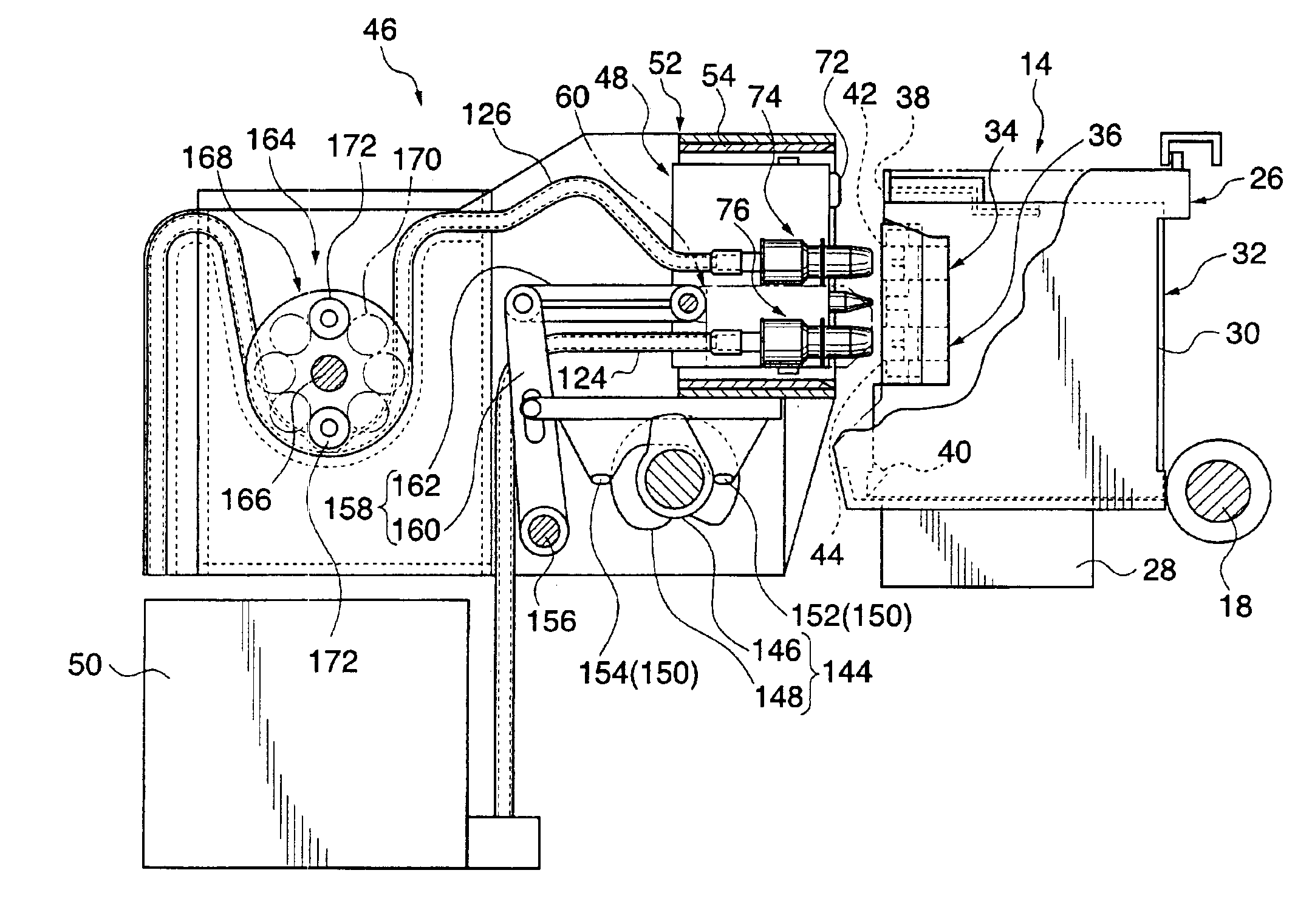
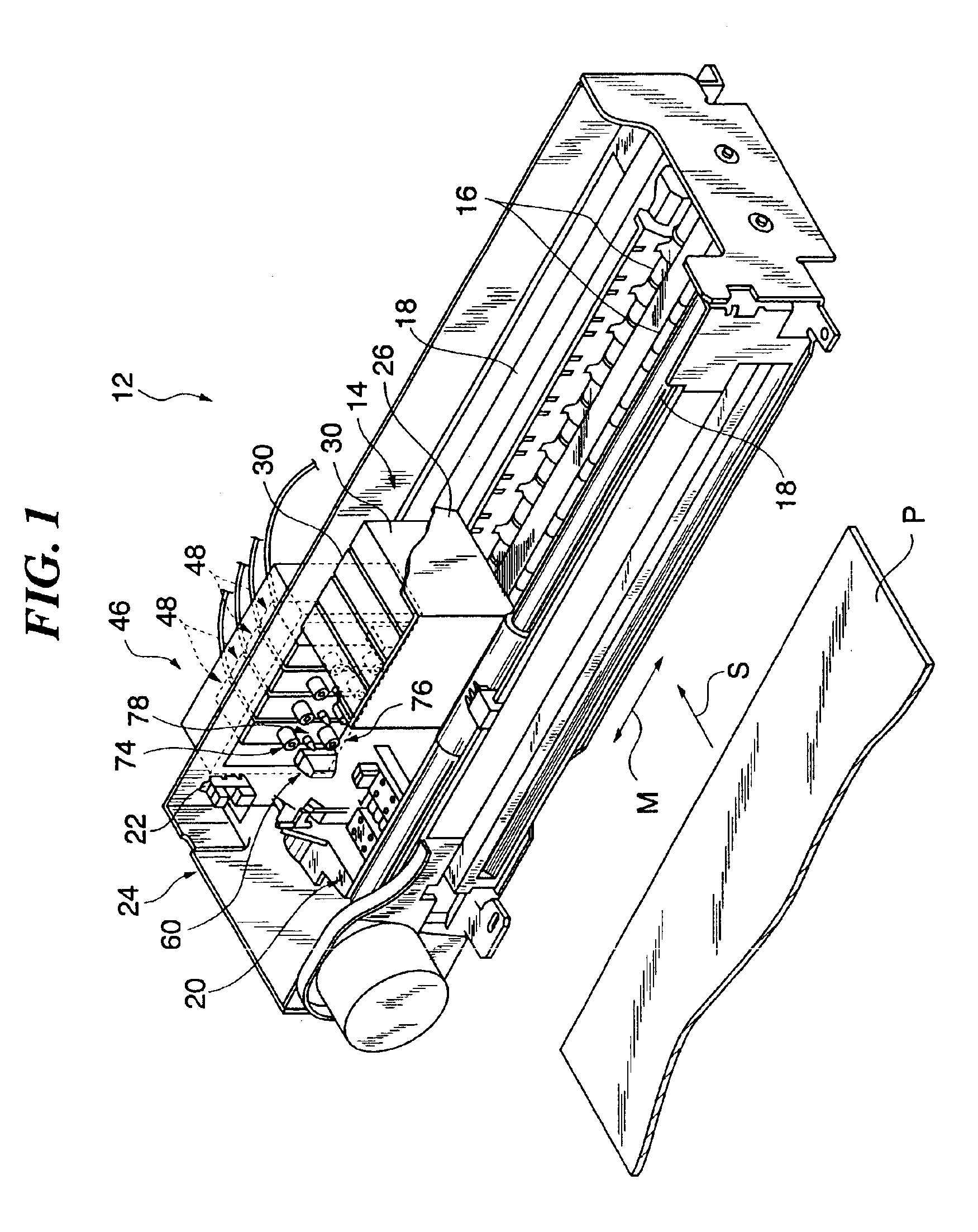
[0061]FIG. 1 illustrates an ink-jet recording device 12 of the first embodiment of this invention, in which a recording head carriage 14 and its neighboring area are enlarged.

[0062]The ink-jet recording device 12 includes a recording medium conveyance member 16 that conveys a recording medium P (for example, paper) in a fixed direction, and a pair of guide members 18 installed along a direction perpendicular to the conveyance direction of the recording medium P so as to face the conveyance route of the recording medium P. These guide members 18 support a recording head carriage 14. Further, a maintenance station 20 underlies the guide members 18 near the conveyance route of the recording medium P, which comes into contact and becomes disjoined with the recording head carriage 14 (moves up and down in this embodiment) to perform a maintenance operation of capping and suction of ink, etc. A control circuit not illustrated controls this maintenance operation in accordance with a specif...


PUM


Abstract

An ink supply device is provided in correspondence with a recording head unit. The recording head unit has a recording head that ejects ink drops onto a recording medium on the basis of image information. Additionally the recording head unit has a sub ink tank provided with an air communication hole. The ink supply device includes an ink supply unit that supplies ink to the sub ink tank by reducing pressure on the inside of the sub ink tank through a pressure reduction part. A sealing part at least implements sealing of the air communication hole while the ink supply unit is reducing the pressure inside the sub ink tank.

Description

CROSS REFERENCE TO RELATED APPLICATION[0001]This patent application is a continuation application of U.S. application Ser. No. 09 / 981,218, filed Oct. 16, 2001 now U.S. Pat. No. 6,612,689, entitled “INK SUPPLY DEVICE, INK-JET RECORDING DEVICE, AND METHOD OF SUPPLYING INK”, herein incorporated by reference in its entirety.BACKGROUND OF THE INVENTION[0002]1. Field of the Invention[0003]The present invention relates to an ink supply device that supplies ink into a sub ink tank of a recording head unit, an ink-jet recording device having the ink supply device, and a method of supplying ink.[0004]2. Description of the Related Art[0005]In the ink-jet recording device that ejects ink drops on a recording medium such as a paper from recording heads on the basis of image information and records the image, there is such a configuration that mounts the sub ink tanks corresponding to each of the recording heads on a carriage to make the recording heads scan, in which there are various types of p...

Claims


Application Information

Patent Timeline
Patent Type & Authority Patents(United States)
IPC IPC(8): B41J2/175
CPCB41J2/17509B41J2/17556B41J2/17523
Inventor SUENAGA, KOJIISHIZE, TATSUHIROSOGA, MITSUHIDEAMARUME, KATSUSHISEKIYAMA, TAKAAKI
Owner FUJIFILM BUSINESS INNOVATION CORP
Why Eureka
Try Eureka