Machine model estimating device of electric motor control apparatus

a technology of electric motor control and machine model, which is applied in the direction of electric controllers, dynamo-electric gear control, dynamo-electric converter control, etc., can solve the problems of increased equipment cost, time and labor, and required fft analyzer 18/b>

Inactive Publication Date: 2005-06-07
YASKAWA DENKI KK
View PDF10 Cites 8 Cited by
  • Summary
  • Abstract
  • Description
  • Claims
  • Application Information

AI Technical Summary

Benefits of technology

[0009]In order to solve the problems, a first aspect of the invention is directed to a machine model estimating device of an electric motor control apparatus comprising an electric motor for driving a load machine, a rotation detector for detecting a rotating angle of the electric motor, and a servo control device for controlling the electric motor, comprising a calculating device for outputting an operation command signal for operating the electric motor to the servo control device, and frequency characteristic equations for a rigid body model and an N-inertia model (N is an integer which is equal to or greater than 2) which are previously input to the calculating device, wherein the calculating device includes a frequency characteristic measuring section for measuring a frequency characteristic from the operation command signal and a signal of the rotation detector input from the servo control device to the calculating device, a frequency characteristic peak detecting section for automatically calculating protruded shapes to be a resonance frequency and an anti-resonance frequency from a shape of the frequency characteristic measured by the frequency characteristic measuring section, an attenuation estimation value analyzing section for estimating an attenuation from the resonance frequency and the anti-resonance frequency which are detected by the frequency characteristic peak detecting section, a frequency characteristic error calculating section for calculating errors of the frequency characteristics calculated in the frequency characteristic equation for the N-inertia model and the frequency characteristic equation for the rigid body model from the frequency characteristic obtained by the measurement respectively, and a machine model deciding section for comparing a minimum error of a calculated value of the frequency characteristic of the N-inertia model which is obtained in the frequency characteristic error calculating section and a measured value with a minimum error of a calculated value of the frequency characteristic of the rigid body model and a measured value and deciding, as an actual model, either of the models which has a smaller error.
[0010]Moreover, a second aspect of the invention is directed to the machine model estimating device of an electric motor control apparatus according to the first aspect of the invention, wherein the frequency characteristic error calculating section carries out curve fitting of the frequency characteristic obtained from the operation command signal and the signal of the rotation detector to the frequency characteristic equation, thereby calculating an error of the calculated value of the frequency characteristic and the meas

Problems solved by technology

In the conventional art, however, the expensive FFT analyzer 18 is required for measuring the frequency characteristic of the load machine.
T

Method used


Image

  • Machine model estimating device of electric motor control apparatus
  • Machine model estimating device of electric motor control apparatus
  • Machine model estimating device of electric motor control apparatus

Examples


first embodiment

[First Embodiment]

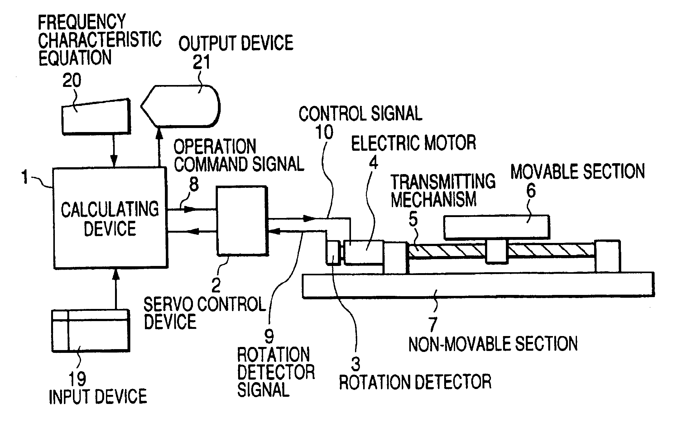
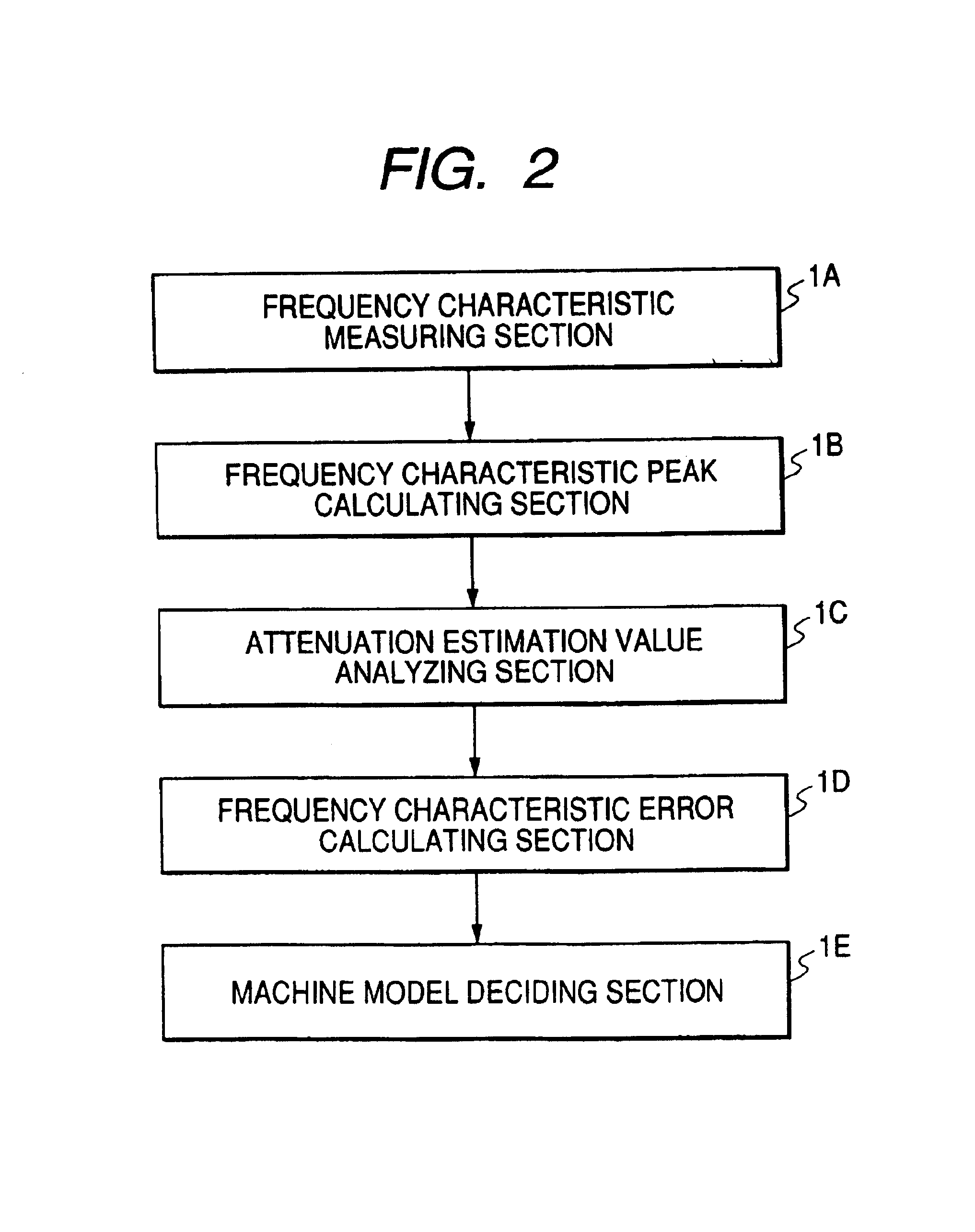
[0029]FIG. 1 is a view showing the whole structure of an electric motor control apparatus comprising a machine model estimating device according to a first embodiment of the invention, and FIG. 2 is a block diagram showing the structure of a calculating device. The same components of the invention as those in the conventional art have the same reference numerals and description thereof will be omitted, and furthermore, only differences will be described.

[0030]In the drawing, 1 denotes a calculating device, 1A denotes a frequency characteristic measuring section, 1B denotes a frequency characteristic peak detecting section, 1C denotes an attenuation estimation value analyzing section, 1D denotes a frequency characteristic error calculating section, 1E denotes a machine model deciding section, 19 denotes an input device, 20 denotes a frequency characteristic equation, and 21 denotes an output device.

[0031]The invention is different from the conventional art as follow...

second embodiment

[Second Embodiment]

[0078]A second embodiment of the invention will be described with reference to the drawings.

[0079]FIG. 14 is a view showing the whole structure of an electric motor control apparatus comprising a machine model estimating device according to the second embodiment of the invention.

[0080]In the drawing, 15 denotes a vibration detector for detecting the operation state of a load machine as a vibration displacement or a vibration acceleration, and 16 denotes a vibration detector signal of the load machine.

[0081]The second embodiment uses the vibration detector 15 in the load machine in place of the rotation detector described in the first embodiment, and can be executed in the same manner as the first embodiment.

[0082]A frequency characteristic Hr from an operation command signal 8 of a rigid body model to the detector 15 is equal to that of the Equation (1). Moreover, a frequency characteristic H′F from the operation command signal 8 of a 2-inertia model to the vibrat...


PUM


Abstract

A machine model estimating device of an electric motor control apparatus having an electric motor for driving a load machine, a rotation detector for detecting a rotating angle of the electric motor, and a servo control device for controlling the electric motor. The machine has a calculating device for outputting an operation command signal for operating the electric motor to the servo control device, and frequency characteristic equations for a rigid body model and an N-inertia model, N being an integer which is equal to or greater than 2, which are previously input to the calculating device. The calculating device includes a frequency characteristic measuring section, a frequency characteristic peak detecting section, an attenuation estimation value analyzing section, a frequency characteristic error calculating section, and a machine model deciding section.

Description

TECHNICAL FIELD[0001]The present invention relates to a machine model estimating device of an electric motor control apparatus which can faithfully estimate a machine model to be easily utilized for a simulation and a servo regulation by automatically reading an anti-resonance frequency, a resonance frequency and an attenuation from a frequency characteristic measured value without using an expensive measuring apparatus even if an operator has neither advanced expertise nor experiences, and is inexpensive.BACKGROUND ART[0002]Conventionally, an electric motor control apparatus to be used in a semiconductor manufacturing apparatus, a positioning apparatus such as a machine tool or an industrial robot is constituted as shown in FIG. 15.[0003]FIG. 15 is a view showing the whole structure of the electric motor control apparatus according to the conventional art, and description will be given by taking a positioning apparatus as an example.[0004]In the drawing, 2 denotes a servo control d...

Claims


Application Information

Patent Timeline
IPC IPC(8): H02P5/00H02P21/13H02P29/00G05B11/36
CPCH02P21/13G05B2219/34048
Inventor KOMIYA, TAKEHIKO
Owner YASKAWA DENKI KK
Why Eureka
Try Eureka