
Format converter using bi-directional motion vector and method thereof

a technology of motion vector and format converter, which is applied in the direction of signal generators with optical-mechanical scanning, instruments, television systems, etc., can solve the problems of affecting the quality of images, complicated signal processing processes and complicated hardware to remove overlaps and holes, and errors that occur in arbitrary fields can be propagated to other fields, so as to improve the quality of pictures

Inactive Publication Date: 2005-05-31
SAMSUNG ELECTRONICS CO LTD
View PDF25 Cites 176 Cited by
  • Summary
  • Abstract
  • Description
  • Claims
  • Application Information

AI Technical Summary

Benefits of technology

[0021]To solve the above problems, it is an object of the present invention to provide a frame rate converting method which refines a picture quality by directly obtaining a bi-directional motion vector of two continuous frames for a pixel to be interpolated.
[0023]It is another object to provide a de-interlacing method wherein by estimating a bi-directional motion vector between two continuous fields for a pixel to be interpolated, the method is easy to perform and has an excellent outline-keeping ability.
[0025]It is another object to provide a de-interlacing apparatus which can enhance reliability of motion information and reduce errors in a pixel to be interpolated by adaptively selecting between motion-compensated interpolation value and spatiotemporal interpolation value according to the degree of motion in an input image.

Problems solved by technology

These overlaps and holes directly affect the picture quality of an image by causing a degradation in the picture quality.
Therefore, for the conventional apparatus, complicated signal processing processes and complicated hardware are necessary to remove the overlaps and holes.
However, since the ELA de-interlacing method does not use motion compensation, flickering occurs in regions where movement exists and, since the TR de-interlacing method is continuously de-interlaced, an error that occurs in an arbitrary field can be propagated to other fields.

Method used


Image

  • Format converter using bi-directional motion vector and method thereof
  • Format converter using bi-directional motion vector and method thereof
  • Format converter using bi-directional motion vector and method thereof

Examples


Embodiment Construction

[0048]Hereinafter, embodiments of the present invention will be described in detail with reference to the attached drawings. The present invention is not restricted to the following embodiments, and many variations are possible within the spirit and scope of the present invention. The embodiments of the present invention are provided in order to more completely explain the present invention to anyone skilled in the art.

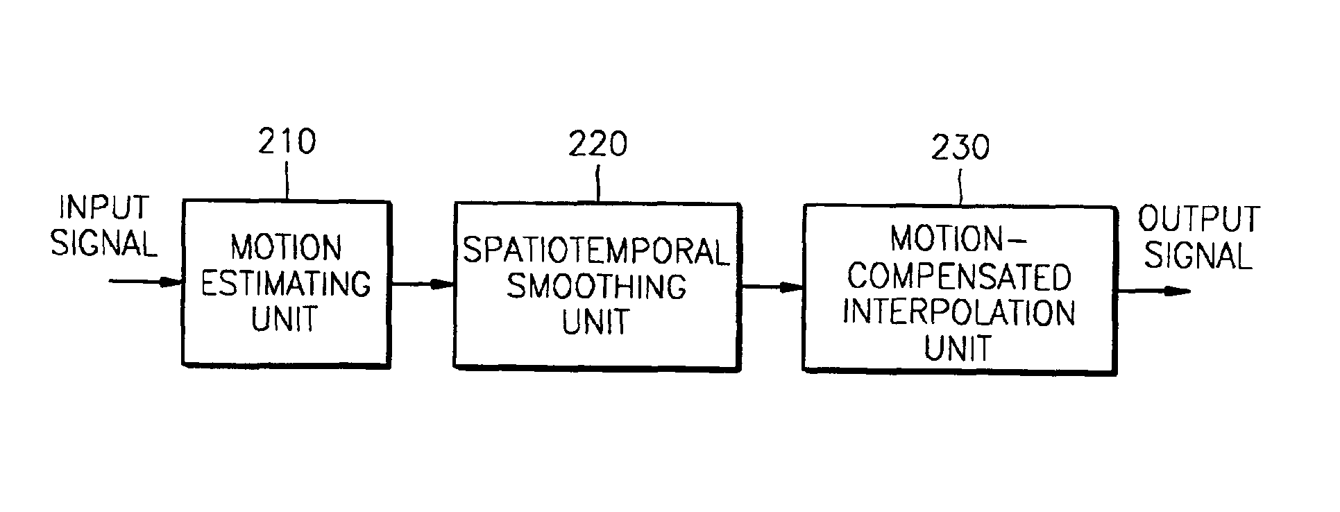
[0049]FIG. 9 is a block diagram of a frame rate conversion apparatus according to the present invention

[0050]The apparatus of FIG. 9 includes a motion estimating unit 210, a spatiotemporal smoothing unit 220, and a refined motion-compensated interpolation unit 230.

[0051]Referring to FIG. 9, the motion estimating unit 210 obtains a motion vector between the current frame and the previous frame, and assigns the motion vector to a frame to be interpolated, and estimates a bi-directional motion vector for the frame to be interpolated.

[0052]The spatiotemporal smoothing uni...


PUM


Abstract

A format converter which performs frame rate conversion and de-interlacing using a bi-directional motion vector and a method thereof are provided. The method includes the steps of (a) estimating a bi-directional motion vector between the current frame and the previous frame from a frame to be interpolated; setting the motion vector of a neighboring block that has the minimum error distortion, among motion vectors estimated in step (a), as the motion vector of the current block; and (c) forming a frame to be interpolated with the motion vector set in step (b).

Description

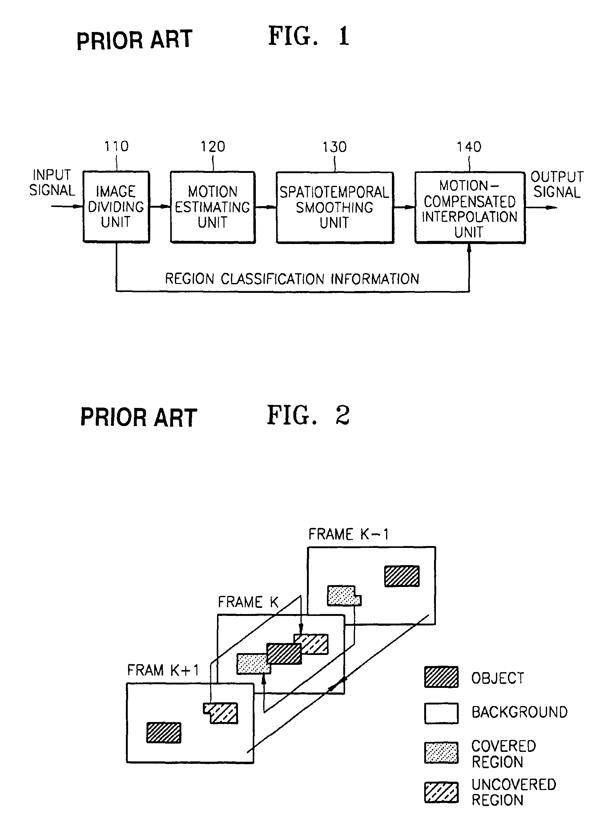
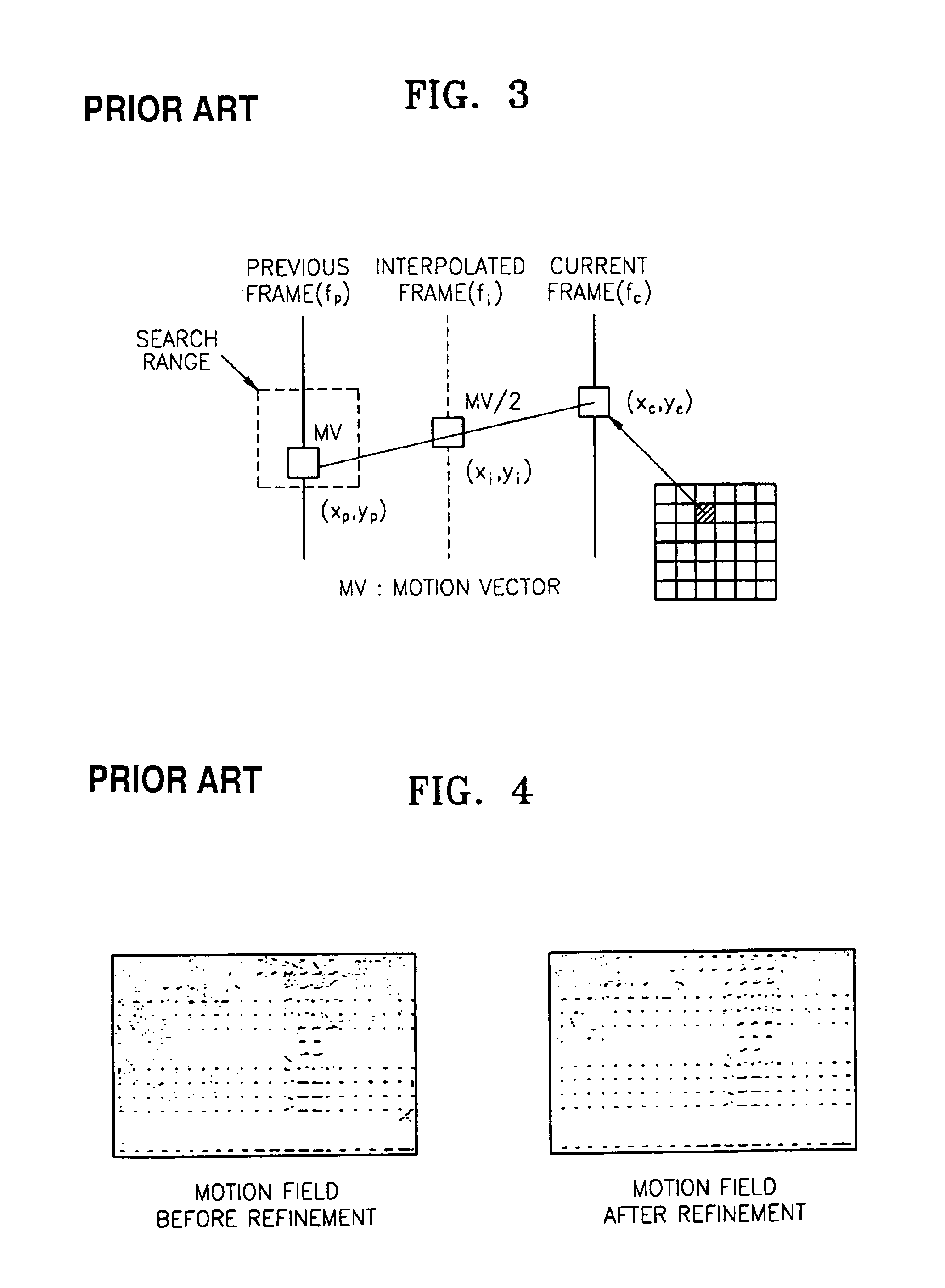
BACKGROUND OF THE INVENTION[0001]1. Field of the Invention[0002]The present invention generally relates to an image signal format converter and an associated method of performing the conversion. More particularly, the invention relates to a format converter, and method, that performs frame rate conversion and de-interlacing using a bi-directional motion vector. The present application is based on Korean Patent Application No. 00-32388 filed on Jun. 13, 2000, which is incorporated herein by reference.[0003]2. Description of the Related Art[0004]Generally, in a PC or a high definition TV (HDTV), conversion of a format such as a frame rate and / or de-interlacing is needed to exchange signals utilizing various signal standards.[0005]FIG. 1 is a block diagram of a conventional frame rate conversion apparatus.[0006]Referring to FIG. 1, an image dividing unit 110 divides an image into a changed region and an unchanged region for efficient motion estimation as shown in FIG. 2. The unchanged ...

Claims


Application Information

Patent Timeline
Patent Type & Authority Patents(United States)
IPC IPC(8): H04N7/01H04N5/44
CPCH04N7/014H04N7/012H04N5/144
Inventor LEE, SUNG-HEEKO, SUNG-JEA
Owner SAMSUNG ELECTRONICS CO LTD
Learn More