DC-DC converter with feed-forward and feedback control
a technology of dc converter and output voltage, which is applied in the control arrangement of secondary cells, battery/fuel cells, instruments, etc., can solve the problem that the feedback control of output voltage cannot cope with such sudden voltage change of high-voltage batteries
- Summary
- Abstract
- Description
- Claims
- Application Information
AI Technical Summary
Benefits of technology
Problems solved by technology
Method used
Image

Examples
first embodiment
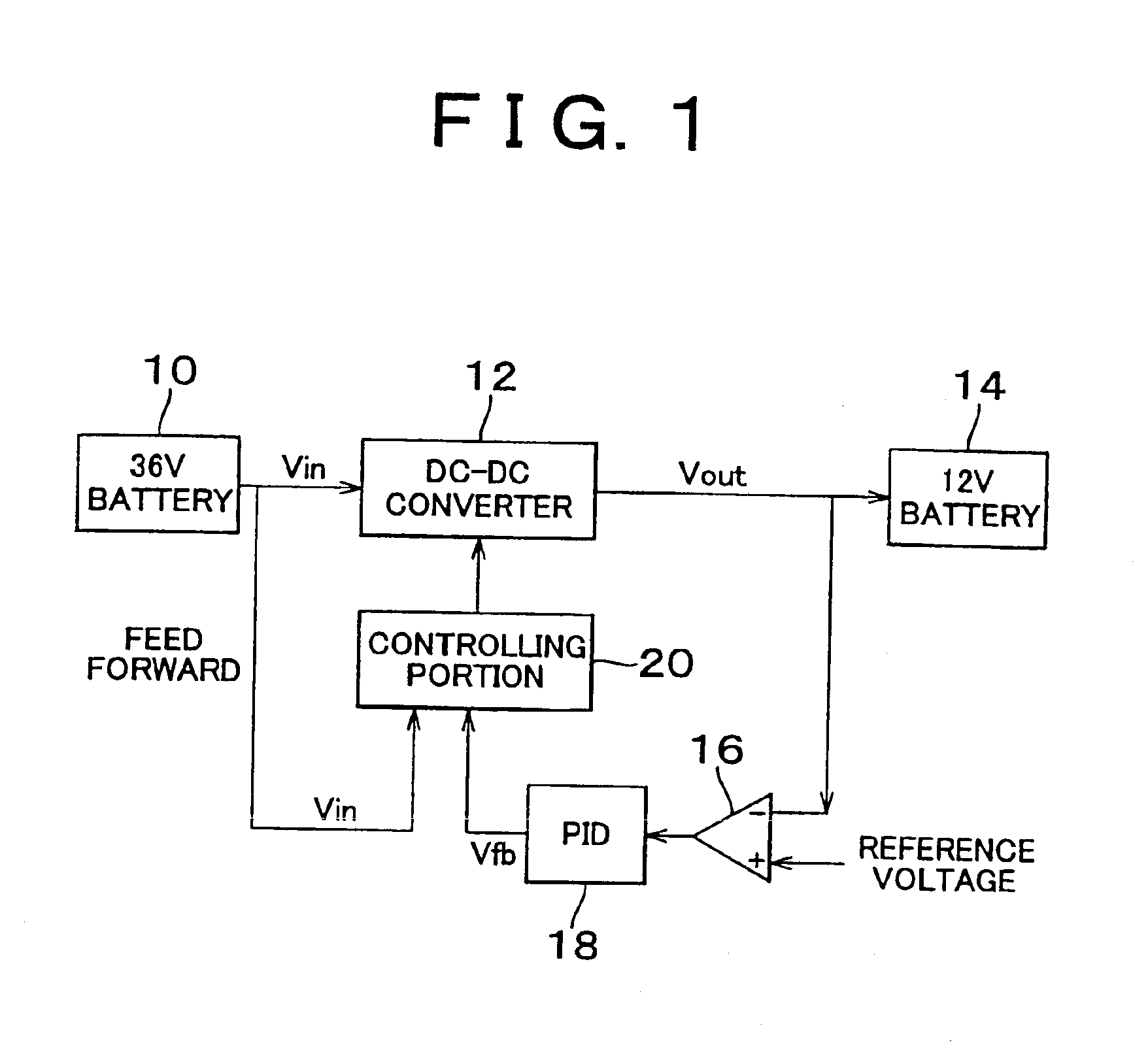
[0027]In FIG. 1 the circuit structure according to the invention is shown. 36-volt battery 10 and 12-volt battery 14 are provided as a high and a low battery, respectively. A DC—DC converter 12 is connected between the 36-volt battery 10 and the 12-volt battery 14. In this embodiment, the DC—DC converter 12 is a type of chopper DC—DC converter which converts 36-volt to 12-volt by controlling two switches to open and close. The two switches are controlled to open and close by a control signal from a controlling portion 20. The control portion 20 feed forward controls the two switches by inputting a voltage Vin from the 36-V battery 10 and feedback controls by returning a portion of an output voltage Vout of the DC—DC converter 12 via a differential amplifier 16 and PID circuit 18.
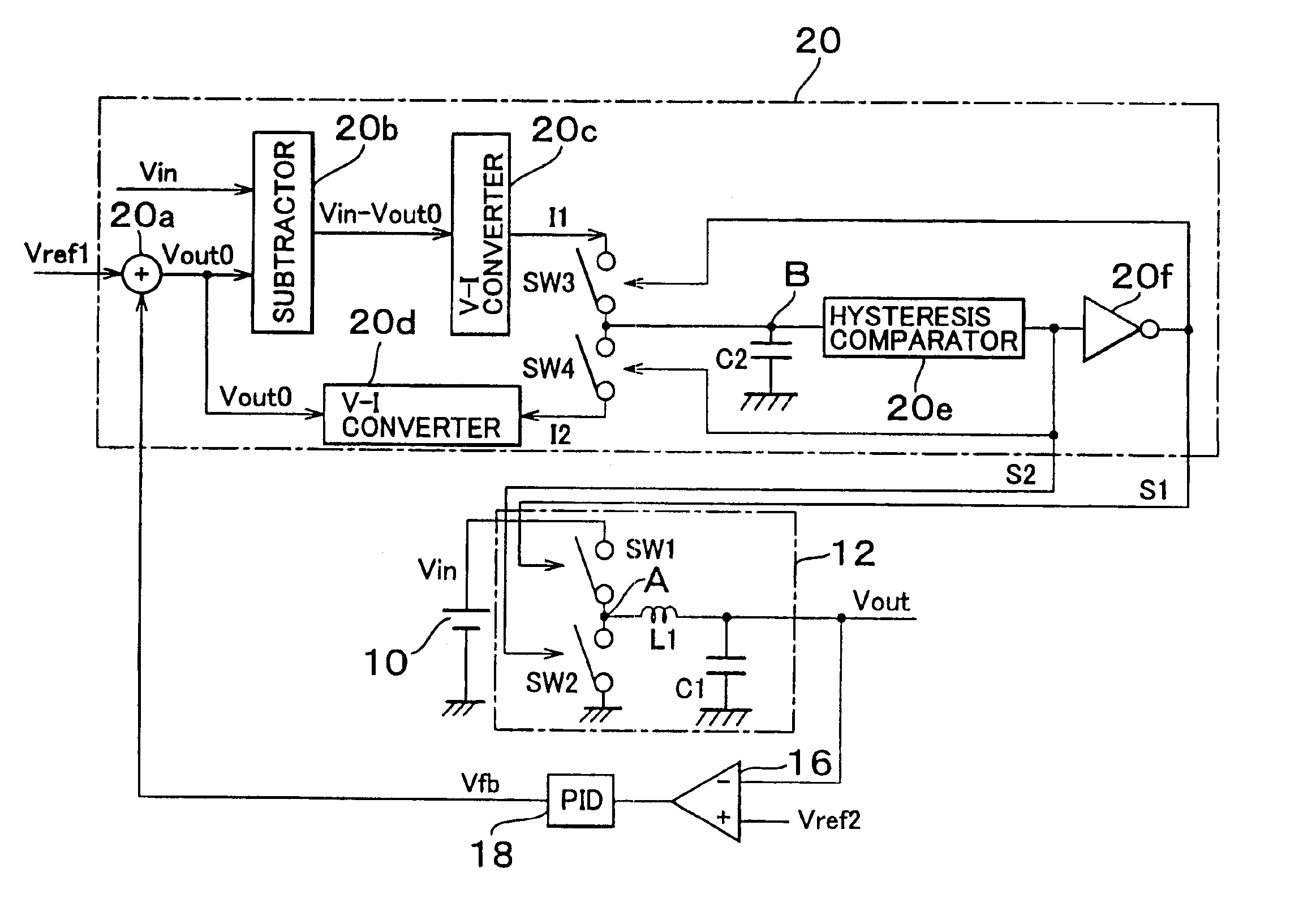
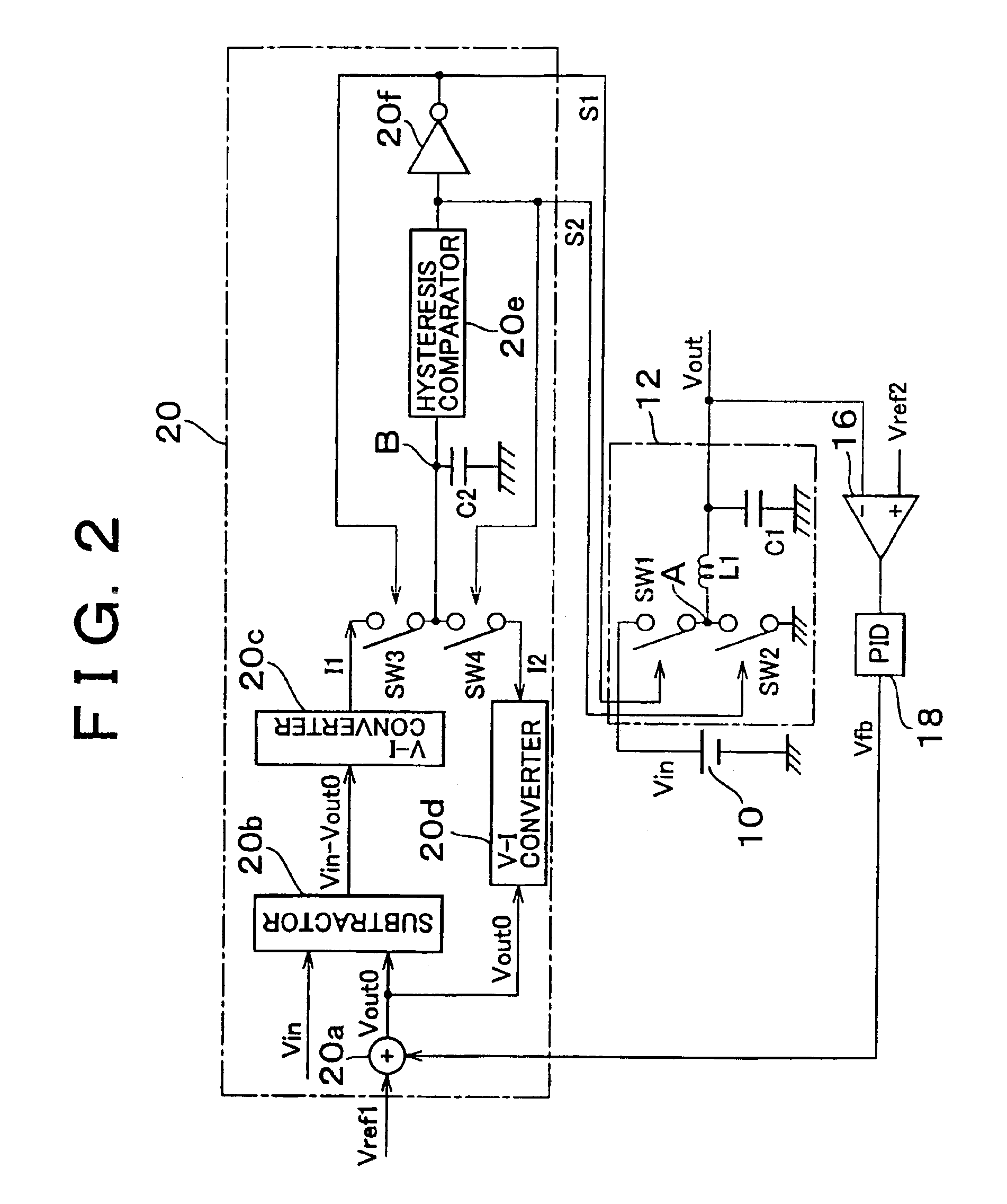
[0028]In FIG. 2, the detail of the circuit of DC—DC converter 12 and the controlling portion 20 in FIG. 1 is shown. First, the detail of the DC—DC converter 12 is explained. The DC—DC converter 12 includes a...
third embodiment
[0052]Next, the invention will be explained with reference to FIG. 8. The system of the aforementioned embodiments uses two switches SW1 and SW2 of the DC—DC converter 12, but the invention is not limited to such system but to be applicable to the DC—DC converter with one switch. In this case the timing t1 corresponds to the closing timing of the single switch and the timing of t2 corresponds to the opening timing of the switch.
[0053]FIG. 8 shows a circuit structure with the DC—DC converter 12 having a single switch. The difference with the circuit in FIG. 2 is that the switch SW2 in FIG. 2 is substituted by a diode D. In this case, the switch SW1 is ON for the timing of t1 and is OFF for the timing of t2 to operate the system similar to FIG. 2. When the switch SW1 becomes OFF from the ON condition, the current continuously flows through coil L1 in the right direction as viewed in FIG. 8 to turn the diode D ON to function as the switch SW2 in FIG. 2.
fourth embodiment
[0054]Next, the invention will be explained with reference to FIGS. 9 and 10. The chopper type DC—DC converter 12 is used in the previous embodiments, but the invention is not limited to the chopper type and any different type, for example, forward type DC—DC converter can be applicable to this invention.
[0055]In FIG. 9, a forward type DC—DC converter circuit is shown. The DC—DC converter 12 is formed by one single switch SW1, transformer, diodes D1 and D2, coil, and condenser. One end of the switch SW1 is connected to a high voltage battery and the other end is connected to the primary side of the transformer. The wiring of the transformer is N:1 and diode D1, diode D2, coil, and condenser are connected to the secondary side of the transformer.
[0056]According to this structure, the voltage of one Nth of the primary side is outputted at the secondary side. When the switch SW1 is ON for the timing of t1 to increase the voltage at the secondary side, the diode D1 is turned ON to apply...
PUM
 Abstract
Description
Claims
Application Information
 - R&D
- Intellectual Property
- Life Sciences
- Materials
- Tech Scout
- Unparalleled Data Quality
- Higher Quality Content
- 60% Fewer Hallucinations
Browse by: Latest US Patents, China's latest patents, Technical Efficacy Thesaurus, Application Domain, Technology Topic, Popular Technical Reports.
© 2025 PatSnap. All rights reserved.Legal|Privacy policy|Modern Slavery Act Transparency Statement|Sitemap|About US| Contact US: help@patsnap.com