Slow-wave induction plasma transport

a plasma transport and slow-wave technology, applied in the field of plasma chemistry, can solve the problems of reducing the efficiency of plasma transpor

Inactive Publication Date: 2005-05-24
DANDL RAPHAEL A
View PDF6 Cites 5 Cited by
  • Summary
  • Abstract
  • Description
  • Claims
  • Application Information

AI Technical Summary

Benefits of technology

[0012]An advantage of the present invention is that a plasma transportation system and method are provided for forcing plasmas to flow through ducts in a specified direction while maintaining the plasma electron temperature at a high enough value to compensate for plasma loss to recombination.
[0013]Another advantage of the present invention is that a plasma transportation system and method are provided for controlled high temperature plasma chemical reactions.
[0014]A further advantage of the present invention is that a system and method are provided for plasma processing chamber effluent gas pyrolyzation.
[0015]Another advantage of the present invention is that a plasma transportation system and method are provided for generating robust directed streams of electrically neutral mixtures of energetic ions, energetic neutral atoms, and electrons for surface modification.
[0016]A still further advantage of the present invention is that a plasma transportation system and method are provided for space propulsion engines.
[0017]A further advantage of the present invention is that a system and method are provided for pumping lasers with an efficient coupled pumping medium.

Problems solved by technology

The challenge in many applications is to use the plasmas to do useful work before they cool off.
But that situation often results in compromises being made between what is best for generating the plasma in the first place and what is best for working the plasma once generated.
But long transportation paths can result in a loss of momentum and a cooling down of the plasma.
There is also the problem of how best to pump the plasma from place to place.
But conventional ion-propulsion engines are not highly developed yet and their operation is non-ideal.
Sustaining higher compression ratios seems to require relatively long ducts.
But only limited success has been achieved with short ducts.
Long ducts suffer too much electron cooling through collisions with neutral gas molecules.
The electrically biased electrodes are susceptible to sputtering when exposed to the plasma.

Method used


Image

  • Slow-wave induction plasma transport
  • Slow-wave induction plasma transport
  • Slow-wave induction plasma transport

Examples


Embodiment Construction

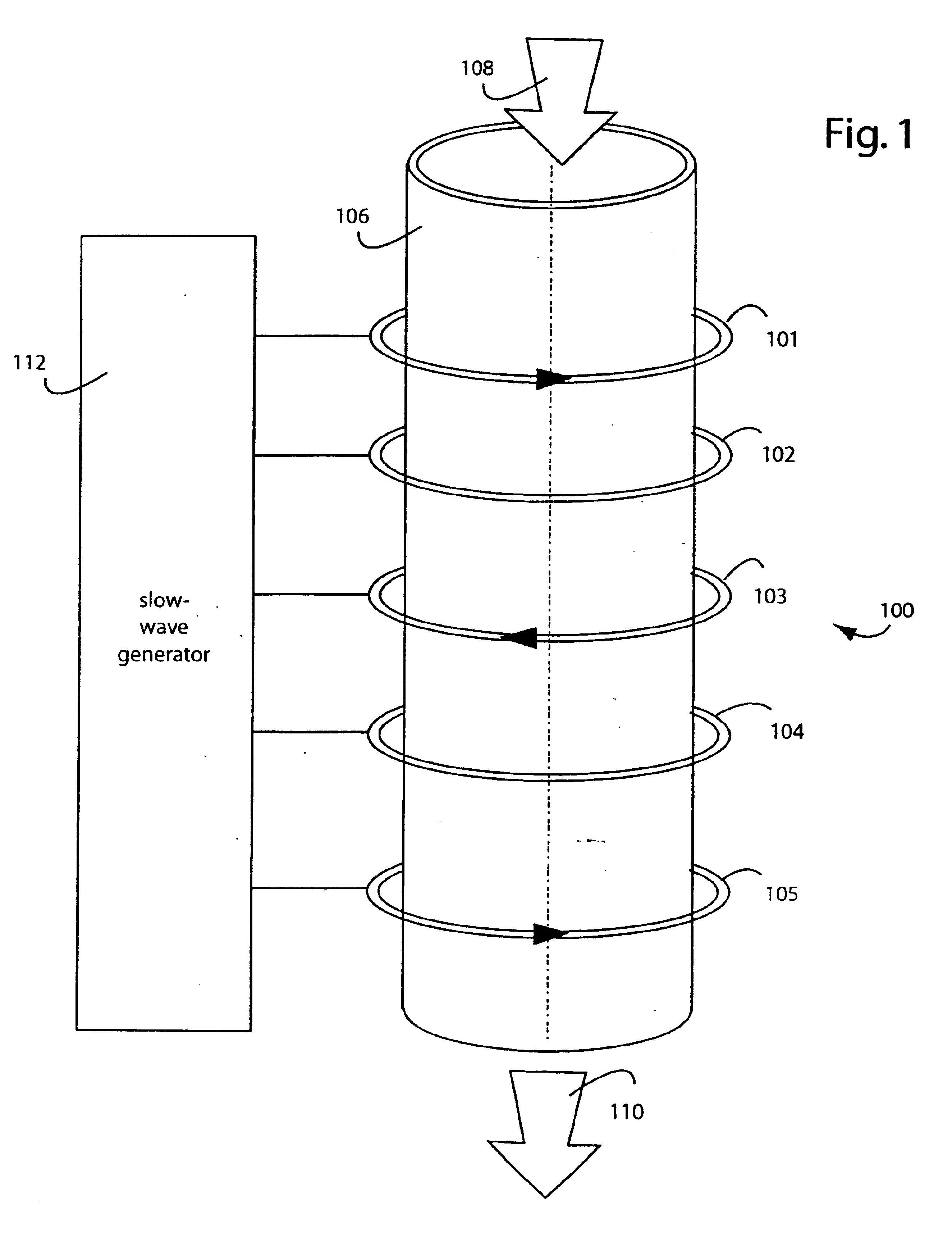
[0023]FIG. 1 represents a plasma transport system embodiment of the present invention, referred to herein by the general reference numeral 100. The system 100 includes a set of five equally spaced coil inductors 101-105 coaxially disposed in a spatial array along the outside of a slow-wave structure 106. The slow-wave structure 106 comprises a hollow cylinder of dielectric material, such as ceramic. The use of five such inductors is simply for illustration in FIG. 1, more such inductors are possible.

[0024]An entering plasma and gas mixture 108 at the top is propelled along inside the duct to become an exiting plasma and gas flow 110. A slow-wave generator 112 produces five sets of signal waveforms to the inductors 101-105 that cooperate to move the plasma and gases along inside. The signal phases between the outputs of the slow-wave generator 112 are separated by π2.

The slow-wave generator 112 drives the plasma and gases along inside by generating five phased RF drive currents, resp...


PUM


Abstract

A plasma transport system uses a slow-wave power signal in external radio-frequency (RF) inductors to force plasmas to flow through ducts, such as from a plasma generator to a point of use. A magneto-hydrodynamic force is deliberately created by the RF inductors to displace plasma electrons down along the inside of the ductwork. A charge separation results that both drags the ions along and slows down the electrons with the ion drag. The consequence is that both electrons and ions are motivated down the ductwork and the overall plasma charge stays neutral. A directed stream of energetic ions and neutral gas atoms can be realized. The RF electric fields induced in the plasma tend to counteract any electron cooling and help maintains the plasma electron temperature enough to reduce later reionization power demands.

Description

BACKGROUND OF THE INVENTION[0001]1. Field of the Invention[0002]The present invention relates to plasma chemistry, and more particularly to devices and methods for transporting and motivating ionized gases which allow a separation of plasma generation and plasma application.[0003]2. Description of Related Art[0004]Plasmas of ionized gases are routinely used in electronics and semiconductor manufacturing. Such plasmas are an almost neutral mix of electrons and ions that will recombine as they cool off. The challenge in many applications is to use the plasmas to do useful work before they cool off. One way to do that is to generate the plasma itself at or near the point of use. But that situation often results in compromises being made between what is best for generating the plasma in the first place and what is best for working the plasma once generated.[0005]It occurs from this that it would be advantageous to generate the plasmas in one area specialized to plasma-generation, and th...

Claims


Application Information

Patent Timeline
Patent Type & Authority Patents(United States)
IPC IPC(8): H01J37/32
CPCH01J37/3266H01J37/32357
Inventor DANDL, RAPHAEL A.
Owner DANDL RAPHAEL A
Why Eureka
Try Eureka