Portable wind power apparatus for electric vehicles

Inactive Publication Date: 2005-05-24
YU XIAOYING
View PDF14 Cites 218 Cited by
  • Summary
  • Abstract
  • Description
  • Claims
  • Application Information

AI Technical Summary

Benefits of technology

[0024]The present invention relates generally to a vehicle and, more specifically, to an electric vehicle that utilizes wind to rotate turbines for converting energy of the wind into electrical energy. The electrical energy is used to provide power to the vehicle as well as to charge and recharge power cells within the vehicle causing the vehicle to selectively move along a desired path. Additionally, the system can be made portable so as to allow flexibility in manufacturing.
[0028]Another object of the present invention is to provide a wind energized electric vehicle whereby the wind turbines positioned on the roof of the vehicle are covered thereby allowing the wind to be concentrated around the turbines and faster rotation of the turbines.
[0029]Still another object of the present invention is to provide a wind energized electric vehicle containing wind turbines that are selectively removable from the roof of the vehicle for upgrade and modification without changing the structure of the electric vehicle, which is inexpensive to manufacture and easy to operate.
[0034]Yet another object of the present invention is to provide a wind energized electric vehicle that is simple and easy to use.

Problems solved by technology

These systems are generally not able to store a sufficient amount of electrical energy to allow the vehicle to be operated as it was designed and the stored energy supply is usually quickly depleted.
These methods of providing energy are not universally viable.
In the case of solar power, the solar panels cannot capture enough energy from the sun to maintain sufficient power in non-sunny conditions thereby restricting the use of these vehicles to specific geographic locales and times of day.
Fuel cells are also not practical as due to the water byproduct formed when employing these types of power sources.
Vehicles that are used in extreme cold could not function properly with these fuel cells as the byproduct would freeze and render the vehicle inoperable.
However, no self-recharging mechanism known in the prior art is able produce enough power to be a viable alternative.

Method used


Image

  • Portable wind power apparatus for electric vehicles
  • Portable wind power apparatus for electric vehicles
  • Portable wind power apparatus for electric vehicles

Examples


Embodiment Construction

[0082]The following discussion describes in detail one embodiment of the present invention. This discussion should not be construed, however, as limiting the invention to those particular embodiments. Practitioners skilled in the art will recognize numerous other embodiments as well. For definition of the complete scope of the invention, the reader is directed to appended claims.

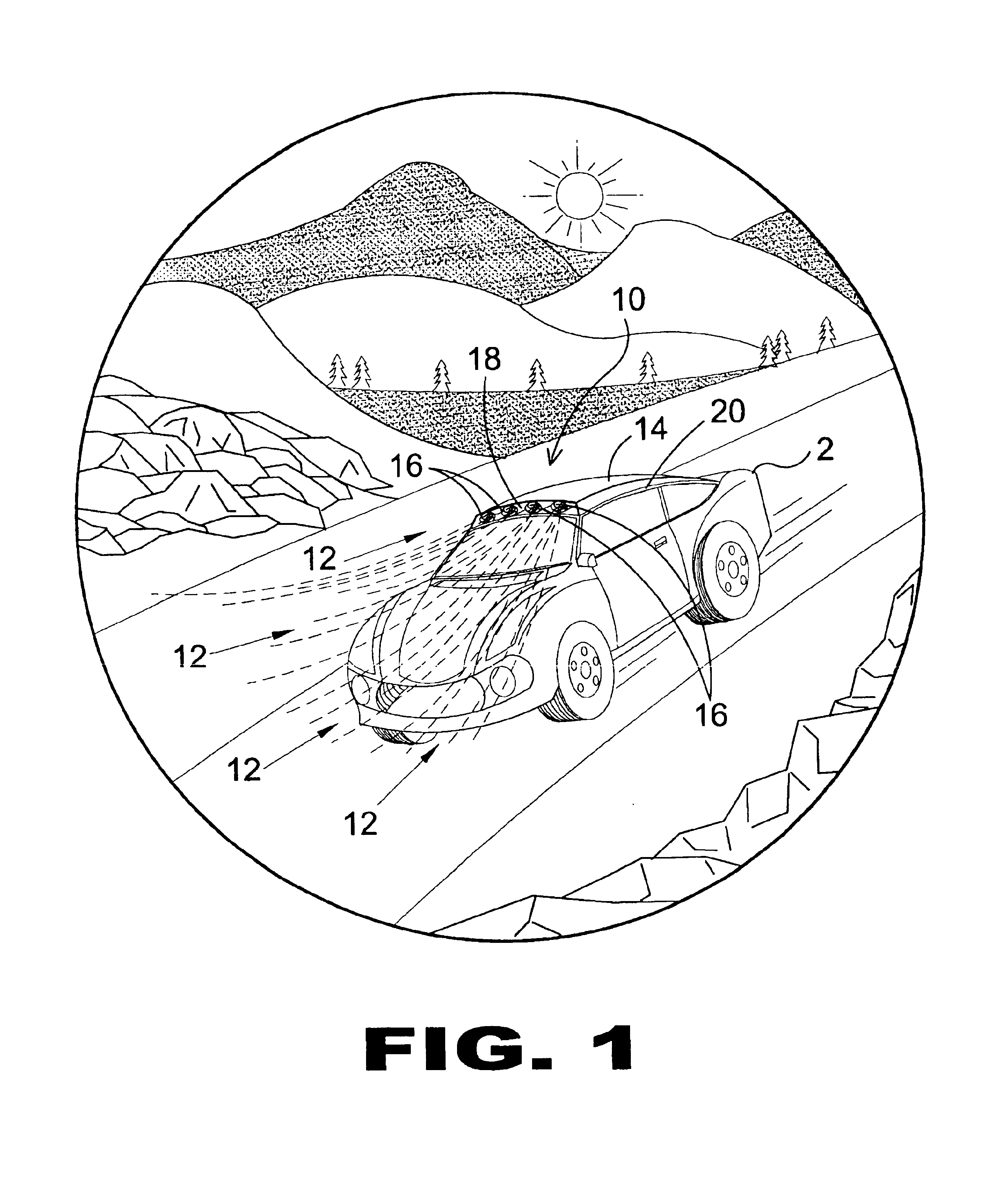
[0083]Turning now descriptively to the drawings, in which similar reference characters denote similar elements throughout the several views, FIGS. 1 through 12 illustrate a portable wind power apparatus of the present invention indicated generally by the numeral 10.

[0084]FIG. 1 is an illustrative view of the portable wind power apparatus of the present invention in use. The portable wind power apparatus 10 is shown positioned at a top of a roof 20 of a vehicle 2. The vehicle 2 is an electric powered vehicle. As will be described hereinafter, the apparatus 10 utilizes wind 12 impingent on the vehicle 2 in ord...


PUM


Abstract

A device for converting wind energy into electrical energy for powering a vehicle, the device including a wind turbine positioned on the vehicle and a generator positioned within the vehicle and connected between the wind turbine and systems of the vehicle. When the vehicle is in motion, wind impinges on the wind turbine and causes the wind turbine to rotate. The generator converts rotational energy of the wind turbine into electrical energy. The electrical energy is provided to power the systems of the vehicle and the batteries of the vehicle are recharged.

Description

BACKGROUND OF THE INVENTION[0001]1. Field of the Invention[0002]The present invention relates generally to a vehicle and, more specifically, to an electric vehicle that utilizes wind to rotate turbines for converting the energy of the wind into electrical energy. The electrical energy is used to provide power to the vehicle as well as to charge and recharge power cells within the vehicle causing the vehicle to selectively move along a desired path.[0003]2. Description of the Prior Art[0004]Numerous other types of electric vehicles exist in the prior art. Prior art electric vehicles include power cells therein for powering a vehicle to move as well as to provide power to operate all sub-systems, such as heat, A / C, and radio, contained within the vehicle. These systems are generally not able to store a sufficient amount of electrical energy to allow the vehicle to be operated as it was designed and the stored energy supply is usually quickly depleted. Therefore, the owners of these ve...

Claims


Application Information

Patent Timeline
IPC IPC(8): B60K16/00F03D11/04
CPCB60K16/00B60L8/006F03D9/002F03D11/04B60K2016/006B60L2210/20B60L2200/26Y02E10/728Y02T10/7083Y02T10/725Y02T10/90Y02E10/725F05B2240/941F03D13/20F03D9/25F03D9/32Y02E10/72Y02T10/72Y02T10/7072
Inventor YU, XIAOYING
Owner YU XIAOYING
Why Eureka
Try Eureka