
Sheet-fed press and intermediate cylinder for sheet-fed press

a technology of intermediate cylinder and sheet-fed press, which is applied in the direction of thin material processing, printing, article separation, etc., can solve the problems of poor drying, uneven drying, and stained or scored printing surfaces, so as to prevent poor drying and the occurrence of stains and scores on the printing surface. , to achieve the effect of easy changing the setting of the press

Inactive Publication Date: 2005-05-24
MITSUBISHI HEAVY IND PRINTING & PACKAGING MACHINERY
View PDF32 Cites 4 Cited by
  • Summary
  • Abstract
  • Description
  • Claims
  • Application Information

AI Technical Summary

Benefits of technology

"The present invention provides a sheet-fed press and an intermediate cylinder that can easily change settings for different sheet sizes. It also prevents poor drying and staining by preventing the sheet from flapping against the intermediate cylinder. The intermediate cylinder has suction boxes and suction bores for generating suction force to hold the sheet in place. The connections between the suction boxes and the suction force generation means can be switched, allowing for easy adjustment of the sheet position. The intermediate cylinder can also have air jet means to stretch the sheet and further improve drying. Combining the intermediate cylinder with a drier can further overcome the problems of poor drying and staining."

Problems solved by technology

Because of this, poor drying such as uneven drying will occur, or the printing surface will be stained or scored.
As a result, flap of the sheet 4 against the intermediate cylinder 3 is caused and the traveling posture of the sheet 4 becomes unstable.(2) Because of the flap of the sheet 4 against the intermediate cylinder 3, the drying effect of the drier 17 is not sufficiently obtained and therefore there is a possibility that poor drying such as uneven drying will occur.(3) If the sheet 4 is separated from the intermediate cylinder 3 because of centrifugal force, etc., the separated rear end portion will make contact with the drier 17, and consequently, the printing surface will be stained or scored.(4) For the above-mentioned reasons, printing quality is considerably reduced and therefore there are cases where a great number of sheets are damaged.
Thus, the exchanging operation is a troublesome operation involving time-consuming efforts.

Method used


Image

  • Sheet-fed press and intermediate cylinder for sheet-fed press
  • Sheet-fed press and intermediate cylinder for sheet-fed press
  • Sheet-fed press and intermediate cylinder for sheet-fed press

Examples


first embodiment

(A) First Embodiment

[0047]FIGS. 2 to 4 show a sheet-fed press constructed in accordance with a first embodiment of the present invention.

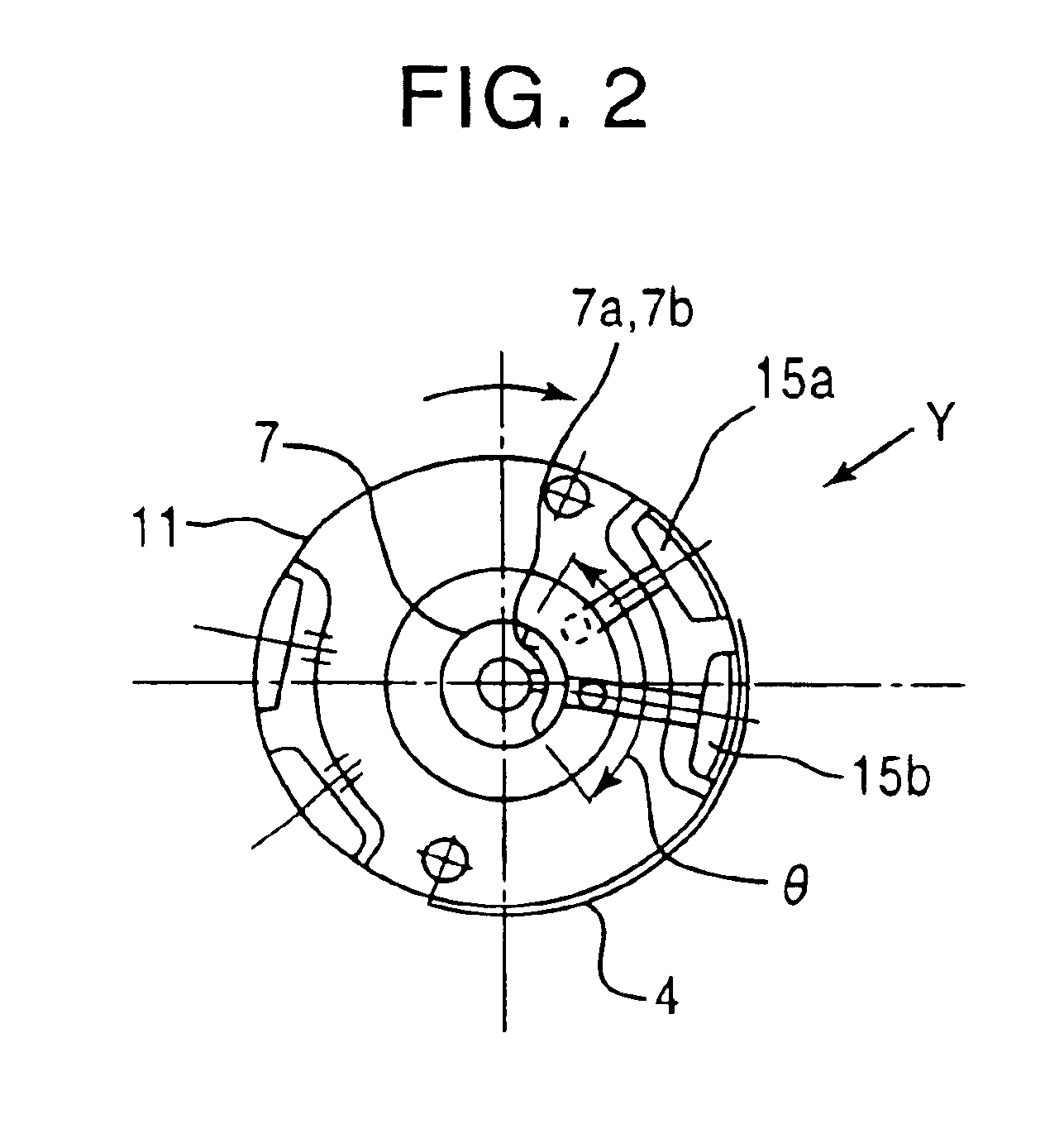
[0048]FIG. 2 is a cross sectional view showing the structure of an intermediate cylinder (suction cylinder) used in the sheet-fed press of the first embodiment, and FIG. 3 is a longitudinal sectional view of the intermediate cylinder. FIG. 4 shows an example of the arrangement of suction bores formed in the intermediate cylinder.

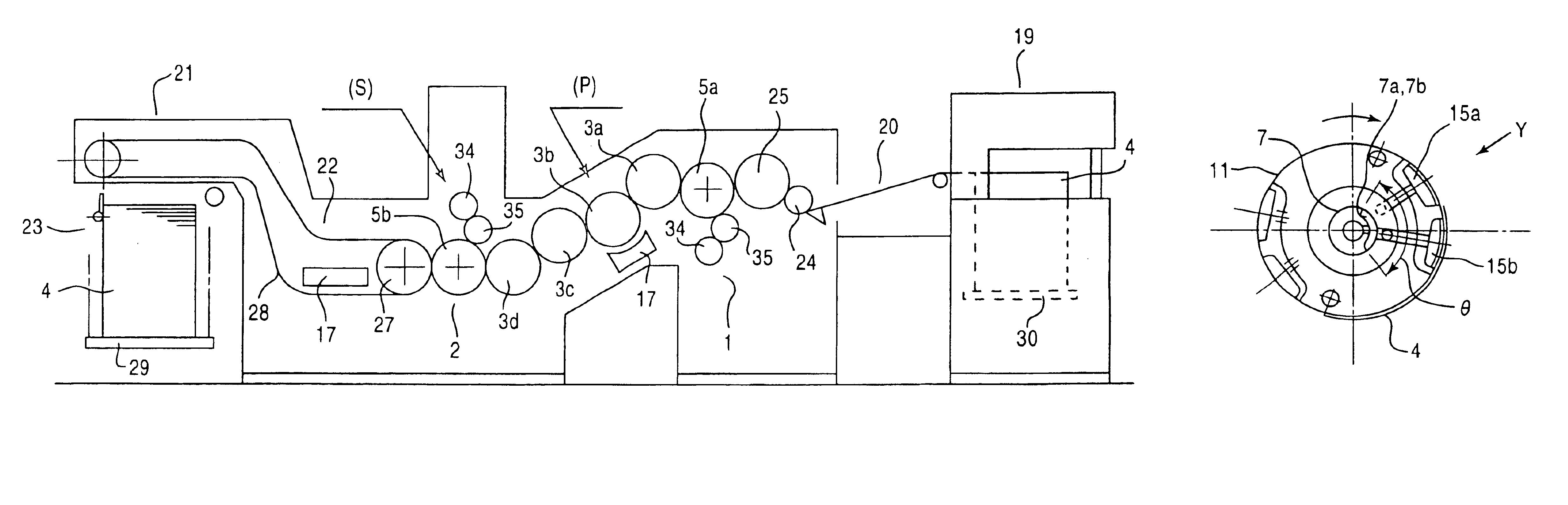
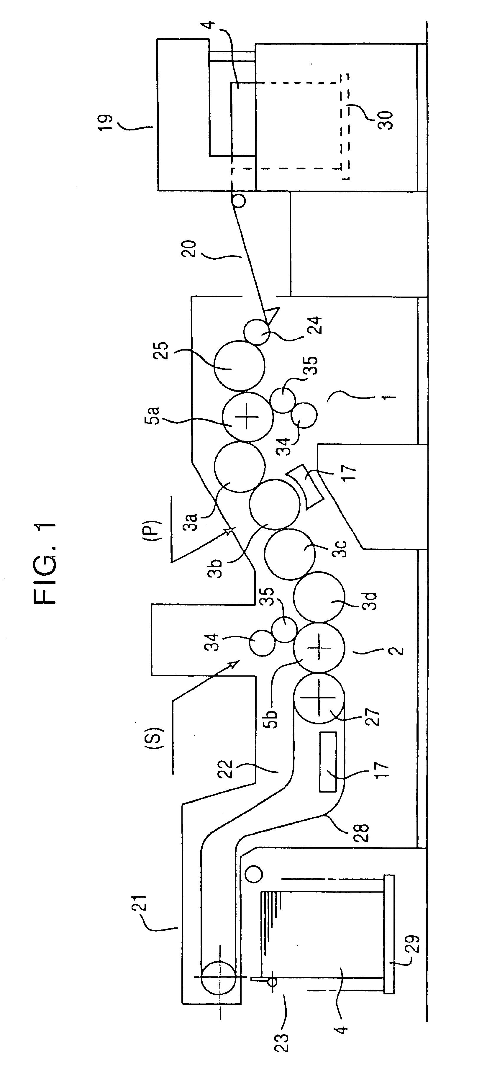
[0049]In the first embodiment, 4 (four) intermediate cylinders 3a to 3d are installed between a reverse-side printing unit 1 and an obverse-side printing unit 2 in FIG. 1, and only the second intermediate cylinder 3b has a suction mechanism which is provided in the outer peripheral surface thereof. That is, the second intermediate cylinder 3b is configured to hold a sheet 4 on the outer peripheral surface thereof by suction to convey the sheet 4 stably. More specifically, the second intermediate cylinder 3b includes a cell ...

second embodiment

(B) Second Embodiment

[0063]FIG. 5 shows a sheet-fed press constructed in accordance with a second embodiment of the present invention. In the second embodiment, two intermediate cylinders (intermediate suction cylinders) according to the present invention are installed in the sheet-fed press.

[0064]As shown in FIG. 5, in a perfecting press constructed to perform one-color printing on both sides of a sheet 4, a second intermediate cylinder 3b and a fourth intermediate cylinder 3d according to the second embodiment are installed between the press cylinder 5a of a reverse-side printing unit 1 and the press cylinder 5b of an obverse-side printing unit 2. In addition, two driers 17 are installed in close proximity to the second and fourth intermediate cylinders 3b and 3d, respectively. The fundamental printing functions are the same as those described in the conventional perfecting press.

[0065]In FIG. 5, two driers 17 are provided and two intermediate cylinders 3b, 3d corresponding to the...

third embodiment

(C) Third Embodiment

[0067]FIGS. 6 to 8 show a sheet-fed press constructed in accordance with a third embodiment of the present invention.

[0068]FIG. 6 is a sectional side view of the sheet-fed press of the third embodiment, FIG. 7 is a perspective view showing the intermediate cylinder and air jet means of the third embodiment, and FIG. 8 is a side view of the intermediate cylinder used for explaining a preferred range of positions where air is jetted by an air shower 50.

[0069]In the sheet-fed press of the third embodiment, as shown in FIG. 6, an air shower 50 as air jet means and an imaging sensor 60 as imaging means (e.g., a CCD camera, a COMS or infrared sensor, etc.) 60 are added to the sheet-fed press of the first embodiment.

[0070]The air shower 50 is provided with a plurality of air jet ports 50a which face a second intermediate cylinder 3b. The second intermediate cylinder 3b is provided with a drier 17 across a traveling line for a sheet 4. As shown in FIG. 7, the air jet por...


PUM


Abstract

An intermediate cylinder comprising a main body, and a plurality of suction boxes formed in the main body at positions different with respect to a rotation axis of the main body. The intermediate cylinder further comprises a plurality of suction bores formed in the suction boxes so that they are open at an outer peripheral surface of the main body, an air suction source for generating suction force within the suction boxes, and a switching means for selectively switching connections between the plurality of suction boxes and the air suction source.

Description

CROSS REFERENCE TO RELATED APPLICATIONS[0001]This application is a divisional application of prior patent application Ser. No. 10 / 193,669 filed on Jul. 12, 2002 now U.S. Pat. No. 6,722,652.BACKGROUND OF THE INVENTION[0002](1) Field of the Invention[0003]The present invention relates generally to an intermediate cylinder for a sheet-fed press, and more particularly to an intermediate cylinder which is installed after a printing unit to adjust the traveling posture of a sheet being fed from the printing unit so that the sheet is stably conveyed. This invention also relates to a sheet-fed press with such an intermediate cylinder.[0004](2) Description of the Related Art[0005]A wide variety of perfecting presses have lately been proposed and put to practical use.[0006]FIG. 9 illustrates a perfecting press of a type where one-color printing is performed on both sides of a sheet 4. This press includes a reverse-side printing unit 1 disposed on the upstream side of a sheet traveling path al...

Claims


Application Information

Patent Timeline
Patent Type & Authority Patents(United States)
IPC IPC(8): B41F21/00B41F25/00B41F21/10
CPCB41F21/10B41F25/00B41F21/102
Inventor KOBAYASHI, SHINYADEJIMA, KAZUTADAHIROSE, HITOSHI
Owner MITSUBISHI HEAVY IND PRINTING & PACKAGING MACHINERY
Learn More