
Fuel injection controller of internal combustion engine

a technology of internal combustion engine and control device, which is applied in the direction of electric control, engine starters, machines/engines, etc., can solve the problems of engine restartability deterioration and fuel leakage from the common rail, so as to improve the restartability of the engine, improve fuel consumption, and reduce the pressure within the common rail

Inactive Publication Date: 2005-05-24
TOYOTA JIDOSHA KK
View PDF22 Cites 4 Cited by
  • Summary
  • Abstract
  • Description
  • Claims
  • Application Information

AI Technical Summary

Benefits of technology

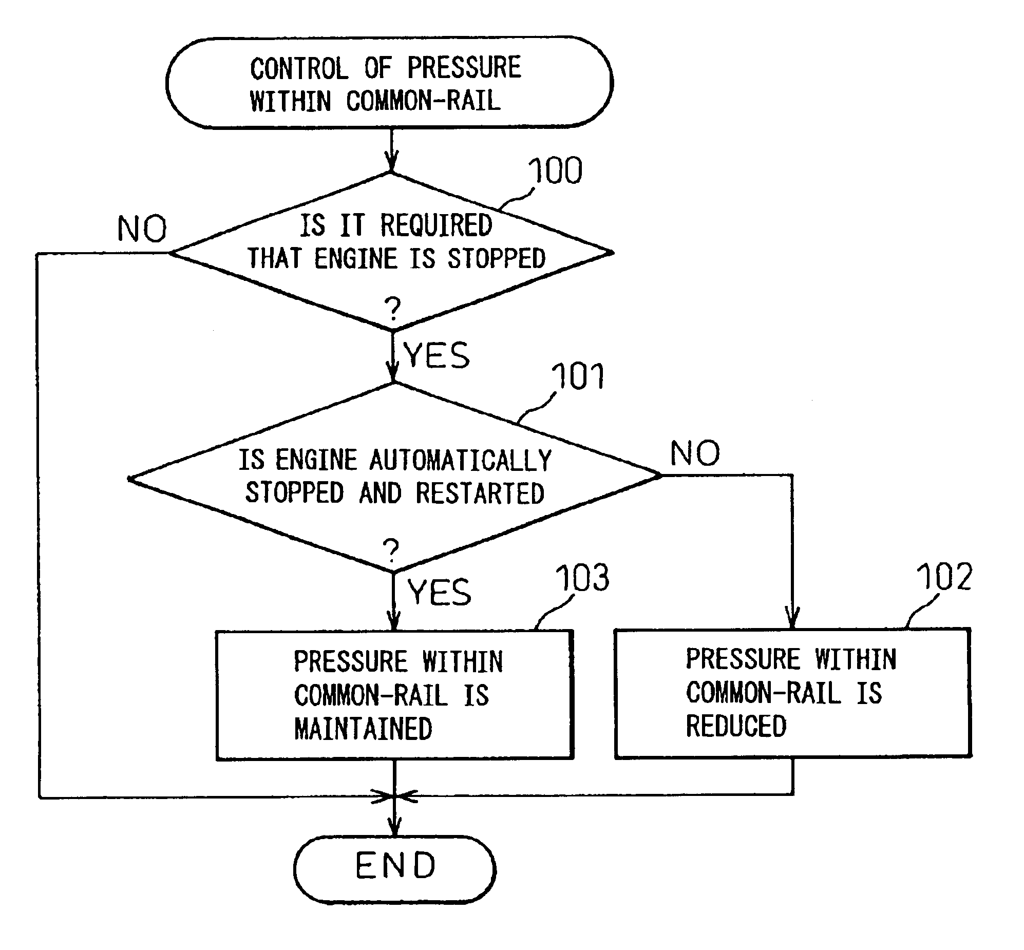
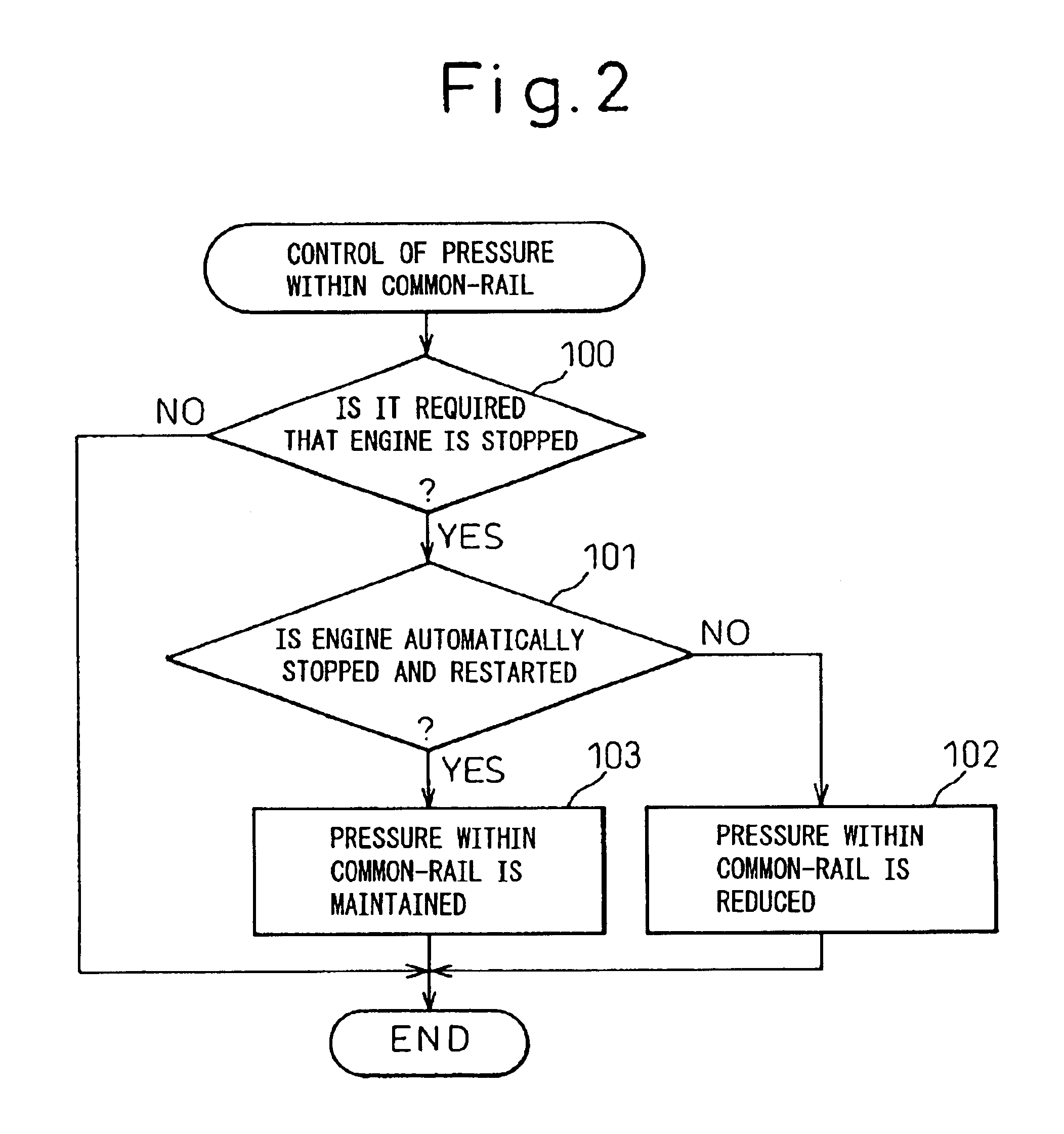
[0005]According to the present invention described in claim 1, there is provided a fuel injection control device for an internal combustion engine comprising a common-rail accumulating pressurized fuel to improve a restartability of the engine, characterized in that it comprises an automatic engine stopping and restarting device for automatically stopping and restarting the engine to improve fuel consumption, the pressure within the common-rail is reduced when the engine is stopped without operating the automatic engine stopping and restarting device, and a reducing amount of the pressure within the common-rail when the engine is stopped by operating the automatic engine stopping and restarting device is made smaller than that when the engine is stopped without operating the automatic engine stopping and restarting device.
[0007]In the fuel injection control device described in claim 1 or 2, the automatic engine stopping and restarting device for automatically stopping and restarting the engine to improve fuel consumption is provided, and the pressure within the common-rail is reduced when the engine is stopped without operating of the automatic engine stopping and restarting device. If the pressure within the common-rail was not reduced when the engine was stopped without operating the automatic engine stopping and restarting device, for example, such that when the ignition switch was turned off, fuel would leak from the common-rail, for example, when the fuel injection control device failed. However, this fuel leakage can be prevented according to the fuel injection control device described in claim 1 or 2. Besides, a falling amount of the pressure within the common-rail when the engine is stopped with operating of the automatic engine stopping and restarting device, is made smaller than that when the engine is stopped without operating of the automatic engine stopping and restarting device. If the pressure within the common-rail was reduced to, for example, zero when the engine was stopped when operating of the automatic engine stopping and restarting device, the engine restartability would deteriorate. However, this deterioration can be prevented according to the fuel injection control device described in claim 1 or 2. Namely, the pressure within the common-rail when the engine stopping is changed over as the engine is stopped with the operation of the automatic engine stopping and restarting device, or without, and thus the pressure within the common-rail during the engine stopping can be made a proper value as the engine is stopped when operating the automatic engine stopping and restarting device, or without. In detail, the engine restartability can be improved when the engine is stopped with operation of the automatic engine stopping and restarting device, and the fuel leakage from the common-rail can be prevented when the engine is stopped without operating of the automatic engine stopping and restarting device.
[0010]The pressure within the common-rail during the engine stopping is preferably kept at a relative high pressure to improve the engine restartability. For example, when the engine is stopped immediately after high-speed running or the like, the pressure within the common-rail at the engine stopping is high. At this time, if the pressure within the common-rail was not reduced during the engine stopping, the pressure within the common-rail at the engine restarting would be too high. Therefore, combustion noise can become large and an amount of emitted HC can become large. In view of this, in the fuel injection control device for an internal combustion engine described in claim 3 or 4, when it is required that the pressure within the common-rail is not reduced to zero during the engine stopping, if the pressure within the common-rail is higher than the target value, the pressure within the common-rail is reduced by the predetermined amount. In detail, when it is required that the engine is stopped with operating of the automatic engine stopping and restarting device for automatically stopping and restarting the engine, if the pressure within the common-rail is higher than the target value, the pressure within the common-rail is reduced by the predetermined amount. Therefore, it can be prevented that, at the engine restarting, combustion noise becomes large and an amount of emitted HC becomes large with a high-pressure within the common-rail at the engine restarting. Namely, the pressure within the common-rail during the engine stopping is made a proper value and thus combustion deterioration at the engine restarting can be restrained.
[0013]When the pressure within the common-rail is reduced before the engine is stopped, fuel is consumed while the pressure within the common-rail is reduced. In view of this, in the fuel injection control device described in claim 5 or 6, when it is required that the pressure within the common-rail is not reduced to zero during the engine stopping, if the pressure within the common-rail is higher than the target value, the pressure within the common-rail is reduced by the predetermined value after the engine has been stopped. In detail, when the engine is stopped with the operation of the automatic engine stopping and restarting device, if the pressure within the common-rail is higher than the target value, the pressure within the common-rail is reduced by the predetermined amount after the engine has been stopped. Namely, the pressure within the common-rail is reduced after the engine has been stopped. Therefore, it can be prevented that fuel consumption deteriorates with a fall in the pressure within the common-rail, before the engine is stopped.

Problems solved by technology

If the pressure within the common-rail was not reduced when the engine was stopped without operating the automatic engine stopping and restarting device, for example, such that when the ignition switch was turned off, fuel would leak from the common-rail, for example, when the fuel injection control device failed.
If the pressure within the common-rail was reduced to, for example, zero when the engine was stopped when operating of the automatic engine stopping and restarting device, the engine restartability would deteriorate.

Method used


Image

  • Fuel injection controller of internal combustion engine
  • Fuel injection controller of internal combustion engine
  • Fuel injection controller of internal combustion engine

Examples


first embodiment

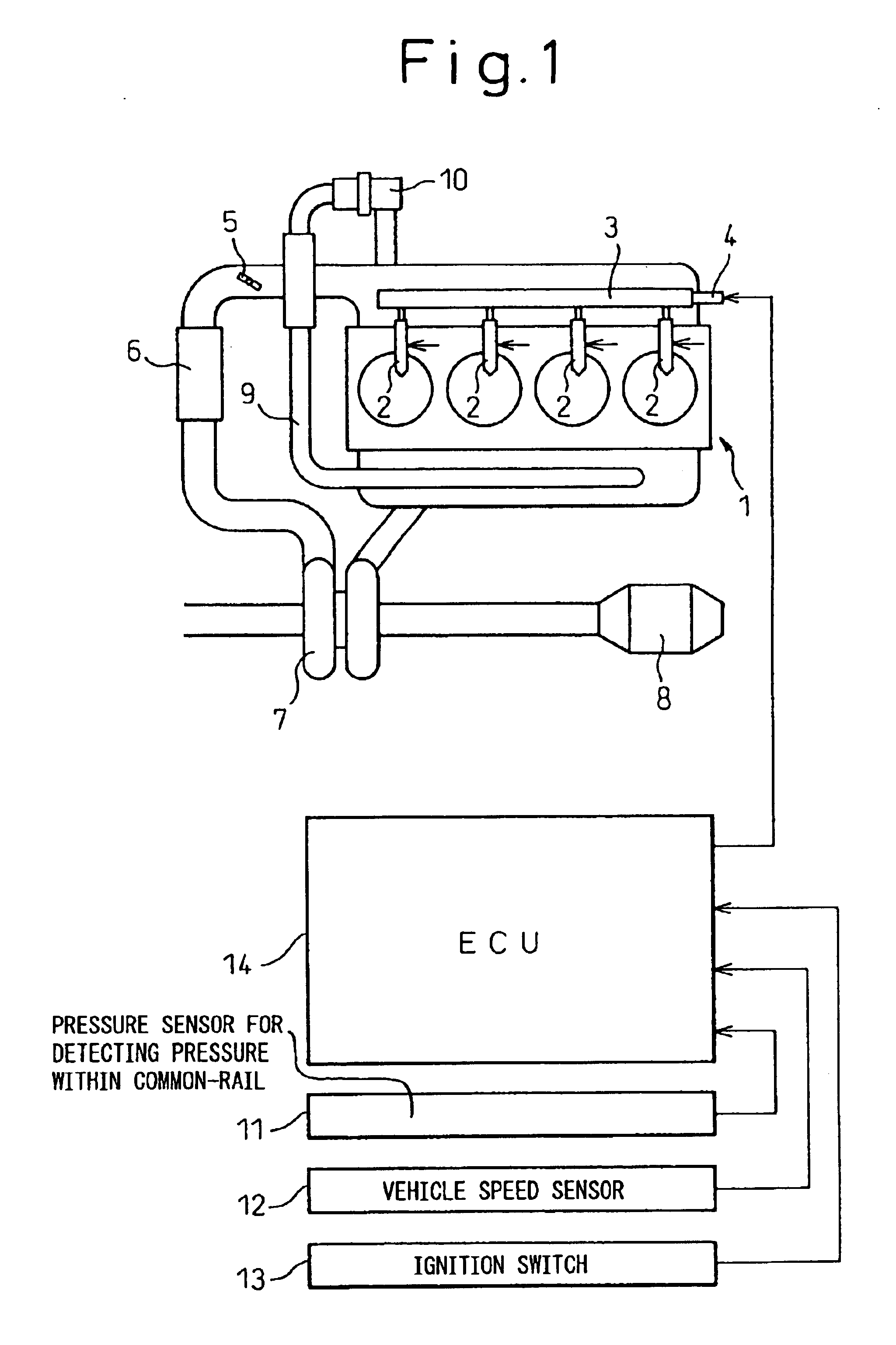
[0020]FIG. 1 is a schematic construction view showing a fuel injection control device for an internal combustion engine according to the present invention. In FIG. 1, reference numeral 1 is an engine body, 2 is a fuel injector for injecting pressurized fuel, and 3 is a common-rail for accumulating pressurized fuel. Fuel is pressurized by a pump (not shown) to be supplied to the common-rail 3. Reference numeral 4 is a pressure-reducing valve 3 for reducing the pressure within the common-rail 3, 5 is a throttle valve, 6 is a intercooler, 7 is a turbo-charger, 8 is a catalytic system for purifying the exhaust gas, 9 is an EGR passage, and 10 is an EGR control valve. Reference numeral 11 is a pressure sensor for detecting the pressure within the common-rail 3, 12 is a vehicle speed sensor, 13 is an ignition switch, and 14 is an ECU (electronic control unit).

[0021]The fuel injection control device for an internal combustion engine of the first embodiment comprises an automatic engine sto...

second embodiment

[0030]Namely, in the second embodiment, the pressure within the common-rail 3 is reduced at step 203 before the engine is stopped with operating of the automatic engine stopping and restarting device. Namely, the pressure within the common-rail 3 is reduced at step 203 before the engine is restarted with an operation of the automatic engine stopping and restarting device.

[0031]The pressure within the common-rail 3 during the engine stopping is preferably maintained relative high to improve the engine restartability. However, when the engine was stopped, for example, immediately after an high speed running of the vehicle, and the pressure within the common-rail 3 at the engine stopping was considerably high, if the pressure within the common-rail 3 was not reduced, the combustion noise would become large and the amount of emitted HC would become large because the pressure within the common-rail 3 would be too high at the engine restarting. In view of this, according to the second emb...

third embodiment

[0037] when it is required that the pressure within the common-rail 3 during the engine stopping is not reduced to zero, if the pressure within the common-rail is higher than the target pressure within the common-rail, the pressure within the common-rail is reduced by the predetermined amount at step 203. In detail, when it is determined at step 300 that it is required that the engine is stopped with an operation of the automatic engine stopping and restarting device and it is determined at step 201 that the actual pressure within the common-rail is higher than the target pressure within the common-rail, the pressure-reducing valve 4 is actuated at step 203 and the pressure within the common-rail is reduced by the predetermined amount. Therefore, it can be prevented that the combustion noise becomes large and the amount of emitted HC becomes large at the engine restarting due to the high pressure within the common-rail at the engine restarting. Namely, the pressure within the common...


PUM


Abstract

The pressure within the common-rail 3 is reduced when the engine is stopped without an operation of the automatic engine stopping and restarting device for automatically stopping and restarting the engine to improve fuel consumption. A reducing amount of the pressure within the common-rail 3 when the engine is stopped with an operation of the automatic engine stopping and restarting device is made smaller than that when the engine is stopped without an operation of the automatic engine stopping and restarting device.

Description

TECHNICAL FIELD[0001]The present invention relates to a fuel injection control device for an internal combustion engine.BACKGROUND ART[0002]A fuel injection control device for an internal combustion engine comprising a common-rail for accumulating pressurized fuel to improve a restartability of an engine, is known. One instance of such a fuel injection control device for an internal combustion engine is disclosed in, for example, Japanese Unexamined Patent Publication No. 10-89178. In the fuel injection control device disclosed in Japanese Unexamined Patent Publication No. 10-89178, a restartability of an engine is improved without making the pressure within the common-rail fall during the engine stopping. In detail, in the fuel injection control device disclosed in Japanese Unexamined Patent Publication No. 10-89178, the pressure within the common-rail is maintained at a predetermined pressure after the engine has stopped.[0003]Thus, as mentioned above, in the fuel injection contro...

Claims


Application Information

Patent Timeline
IPC IPC(8): F02D41/38F02D41/04F02N11/08F02M25/07F02D29/02F02M47/00F02D45/00
CPCF02D41/042F02D41/3836F02B29/0406F02N11/0814F02D2250/31F02M25/0707F02D41/123F02M26/05
Inventor KANEKO, TOMOHIROTOMINAGA, HIROYUKI
Owner TOYOTA JIDOSHA KK
Learn More