V-type engine

a v-type engine and cylinder head technology, which is applied in the direction of machines/engines, mechanical equipment, combustion air/fuel air treatment, etc., can solve the problems of difficult high-temperature restart of v-type engines, limited heat shield capability of thin insulators, and percolation in carburetor, so as to prevent percolation in the carburetor and excellent restartability

Active Publication Date: 2012-03-27
HONDA MOTOR CO LTD
View PDF16 Cites 2 Cited by
  • Summary
  • Abstract
  • Description
  • Claims
  • Application Information

AI Technical Summary

Benefits of technology

[0007]The present invention has been made in consideration of such circumstances, and has an objective of providing a V-type engine that can have excellent restartability in a high-temperature state by surely preventing heat from banks from affecting a carburetor in order to prevent percolation in the carburetor even in the case where the engine stops its operation in a high-temperature state.
[0009]According to the first feature of the present invention, the first and second heat shield plates each define the cooling air passage between the heat shield plate and the corresponding side face of the first and second banks B1 and B2, and cooling air is guided into the cooling air passage while the V-type engine is in operation. Thereby, the banks can be cooled. When the V-type engine in a high-temperature state stops its operation, the first and second heat shield plates interposed between the corresponding first and second banks and the carburetor shield the carburetor from radiation heat from the banks. Furthermore, the carburetor is placed at the valley between the first and second banks while being spaced from the banks, and connected to the banks with the intake pipes, respectively. Accordingly, heat radiation effects of the intake pipes allow less heat to be conducted from the banks to the carburetor. The carburetor can thus be prevented from heating up. Accordingly, percolation in the carburetor can be prevented, and this can contribute to improvement of the restartability of the engine in a high-temperature state.
[0010]As described, the first and second heat shield plates play two functions: guidance of cooling air to the surrounding of the first and second banks while the V-type engine E is in operation; and shielding of the carburetor from radiation heat from the banks when the V-type engine E stops its operation. This can contribute to simplification of the structure around the V-type engine.
[0012]According to the second feature of the present invention, the first and second heat shield plates are integrally connected to each other by the bottom plate to form the single component. Since the single component is integrally formed, not only can the heat shield plates be manufactured at once, this synthetic resin member can be attached to the V-type engine easily and speedily.
[0014]According to the third feature of the present invention, the holding part holding the linear member is integrally formed to the single component. Accordingly, a holding member dedicated to the linear member does not need to be attached to the V-type engine. This can contribute to reduction in the number of components.

Problems solved by technology

Consequently, heat of the banks easily stays in a valley between the first and second banks, which can cause percolation in a carburetor placed in the valley.
The percolation makes it difficult for the V-type engine to restart in a high-temperature state.
However, in the above conventional measure, the carburetor is joined to the banks with the relatively-thin insulators in between, and such thin insulators have a limited heat shield capability.

Method used


Image

  • V-type engine
  • V-type engine
  • V-type engine

Examples


Embodiment Construction

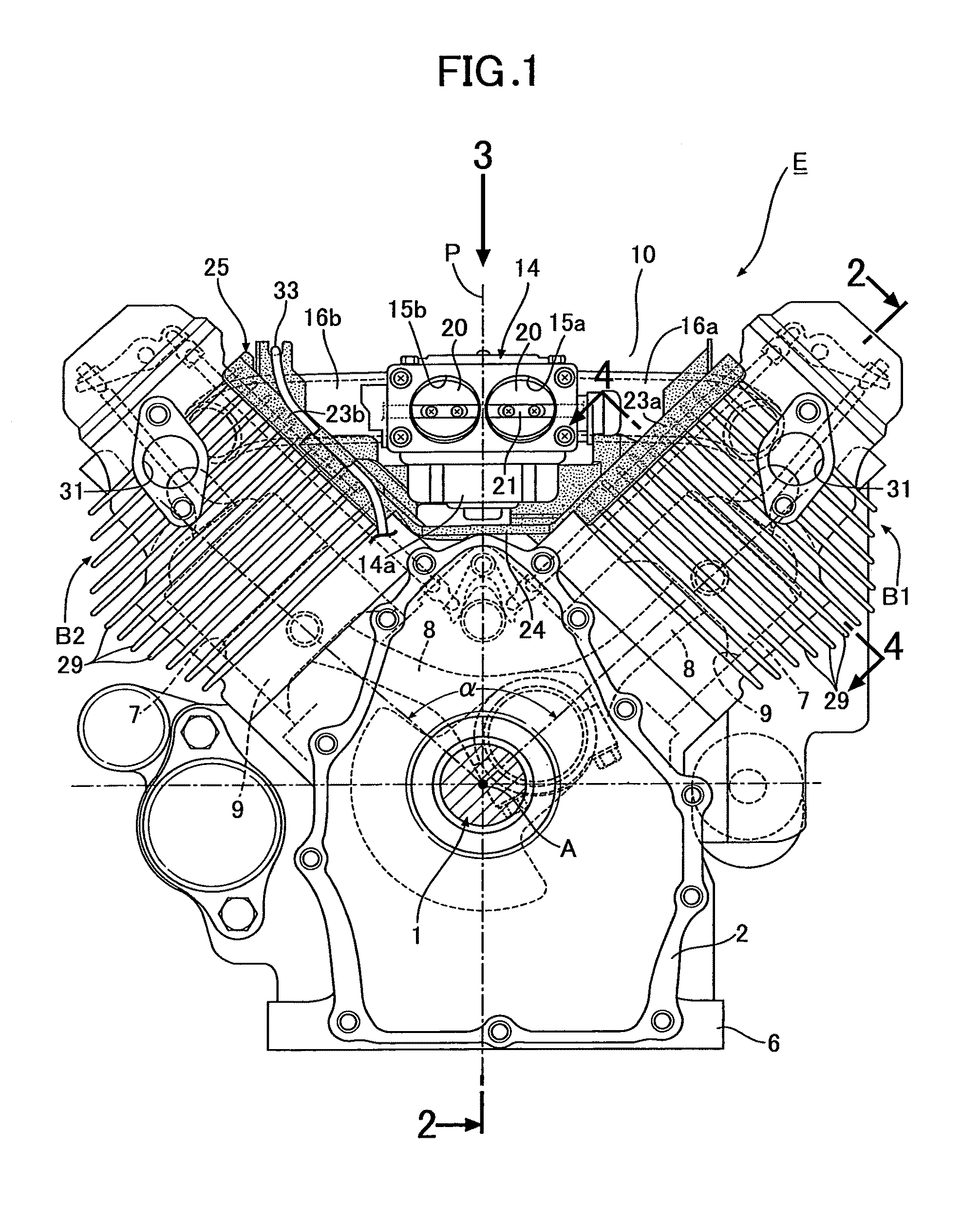
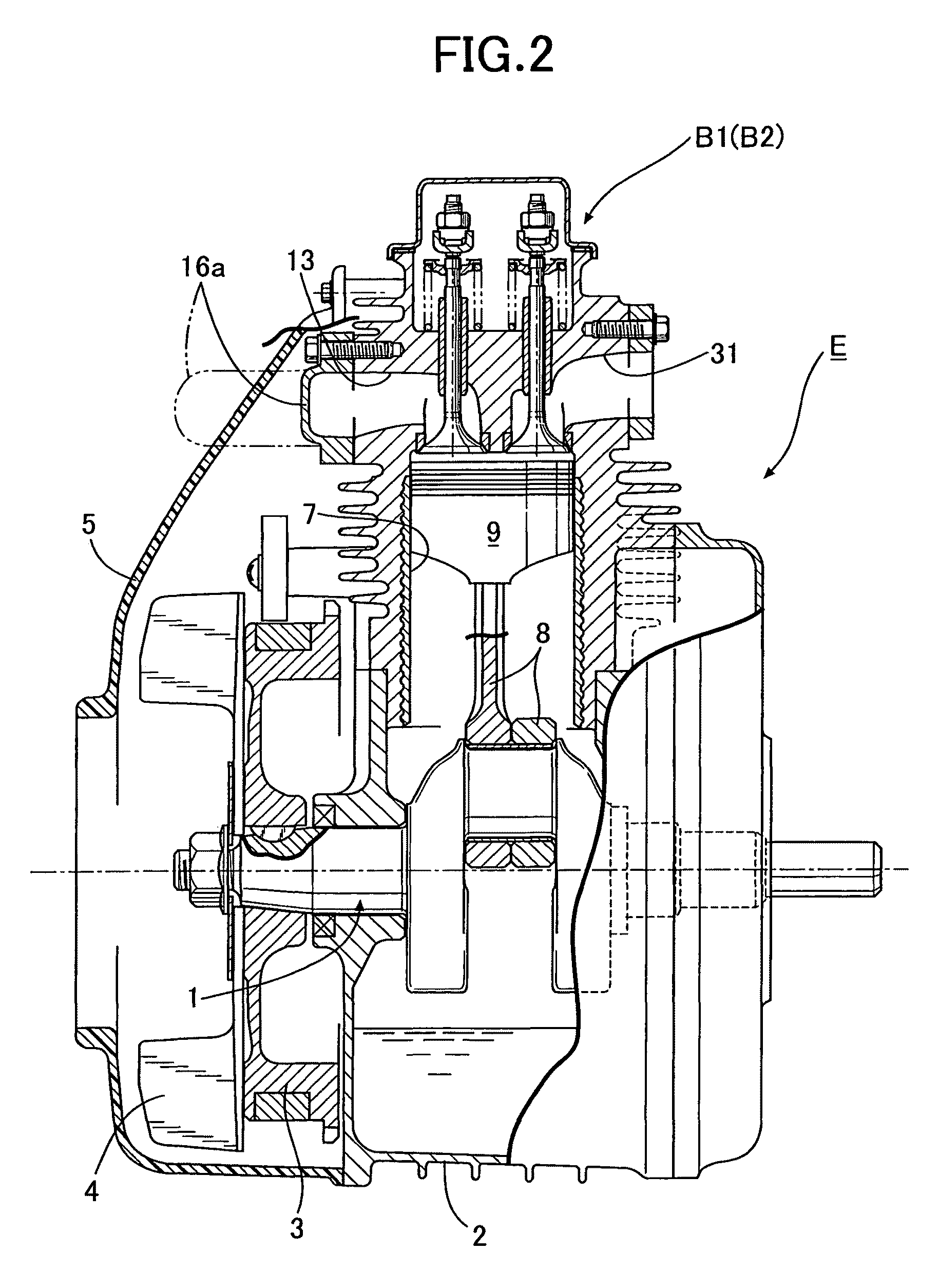
[0023]An embodiment of the present invention will be explained below with reference to FIGS. 1 to 7.

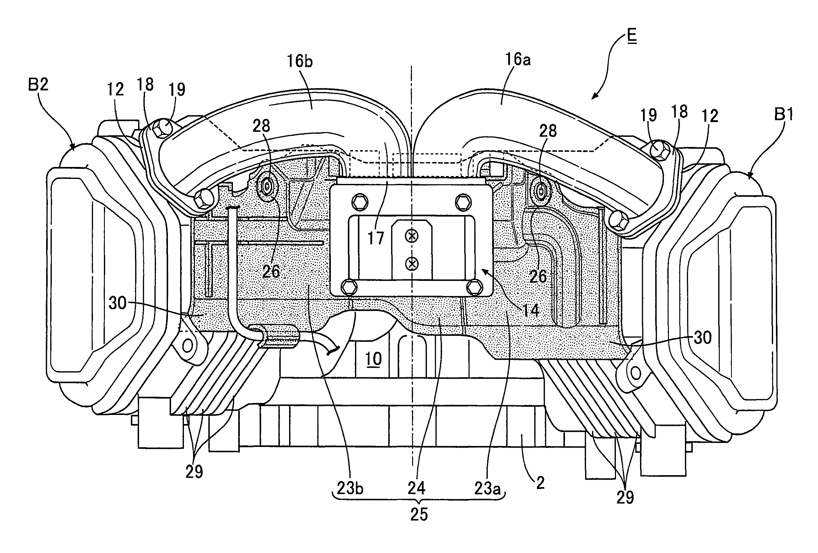
[0024]In FIGS. 1 and 2, a description will be given of an example in which the present invention is implemented to a general-purpose V-type two-cylinder engine E. The V-type engine E is formed of a crankcase 2 supporting a crankshaft 1, and first and second banks B1 and B2. The first and second banks B1 and B2 are continuously provided to the crankcase 2 at a top part, and are open in a V-shape having its center on a vertical plane P including an axis A of the crankshaft 1. In the illustrated example, an included angle α between the first and second banks B1 and B2 is set to 90°. One end part of the crankshaft 1 protrudes frontward of the crankcase 2, and a flywheel 3 and a cooling fan 4 are fixed to this end part. A fan cover 5 is attached to the crankcase 2. By this fan cover 5, the outside air taken in by the cooling fan 4 is guided, as cooling air, to the surrounding of each of th...


PUM


Abstract

In a V-type engine in which first and second banks arranged in a V-shape are provided continuously to a crankcase, and in which a carburetor is placed at a valley between the first and second banks, the carburetor is placed spaced from the first and second banks. Further, the carburetor is connected to intake ports of the first and second banks via first and second intake pipes, respectively, and first and second heat shield plates each made of synthetic resin are attached to side faces of the respective first and second banks, the side faces facing the carburetor, each of the first and second heat shield plates covering a corresponding one of the side faces and defining a cooling air passage between the heat shield plate and the side face. Accordingly, it is possible to surely prevent heat from the banks from affecting the carburetor in order to prevent percolation in the carburetor even in the case where the engine stops its operation in a high-temperature state.

Description

CROSS-REFERENCE TO RELATED APPLICATIONS[0001]The present invention claims priority under 35 USC §119 based on Japanese patent application No. 2008-146531 filed Jun. 4, 2008. The subject matter of this priority document is incorporated by reference herein.BACKGROUND OF THE INVENTION[0002]1. Field of the Invention[0003]The present invention relates to an improvement of a V-type engine in which first and second banks arranged in a V-shape are provided continuously to a crankcase, and in which a carburetor is placed at a valley between the first and second banks, the carburetor communicating with intake ports of the respective banks.[0004]2. Description of the Related Art[0005]Immediately after such a V-type engine stops its operation, cooling air stops flowing. Consequently, heat of the banks easily stays in a valley between the first and second banks, which can cause percolation in a carburetor placed in the valley. The percolation makes it difficult for the V-type engine to restart i...

Claims


Application Information

Patent Timeline
Patent Type & Authority Patents(United States)
IPC IPC(8): F02B75/22
CPCF02B75/22F02B77/11F02M15/06
Inventor OGAWA, KAZUHISAHASHIMOTO, MANABU
Owner HONDA MOTOR CO LTD
Why Eureka
Try Eureka