Internal Combustion Engine Control Device and Internal Combustion Engine Control System

a control device and control system technology, applied in the direction of machines/engines, non-mechanical valves, output power, etc., can solve the problems of difficult to ensure a good restartability, control device requires a comparatively long time duration, and the vtc mechanism exhibits a bad operational responsiveness at very low engine speed, so as to achieve good engine restartability

Inactive Publication Date: 2011-04-21
HITACHI AUTOMOTIVE SYST LTD
View PDF17 Cites 16 Cited by
  • Summary
  • Abstract
  • Description
  • Claims
  • Application Information

AI Technical Summary

Benefits of technology

[0005]It is, therefore, in view of the previously-described disadvantages of the prior art, an object of the invention to provide a control device or a control system configured to control a variable valve actuation device in such a manner as to bring an...

Problems solved by technology

Thus, when cranking the engine, the VTC mechanism must be operated greatly, but the VTC mechanism exhibits a bad operational responsiveness at very low engine speeds.
Such a c...

Method used


Image

  • Internal Combustion Engine Control Device and Internal Combustion Engine Control System
  • Internal Combustion Engine Control Device and Internal Combustion Engine Control System
  • Internal Combustion Engine Control Device and Internal Combustion Engine Control System

Examples


first embodiment

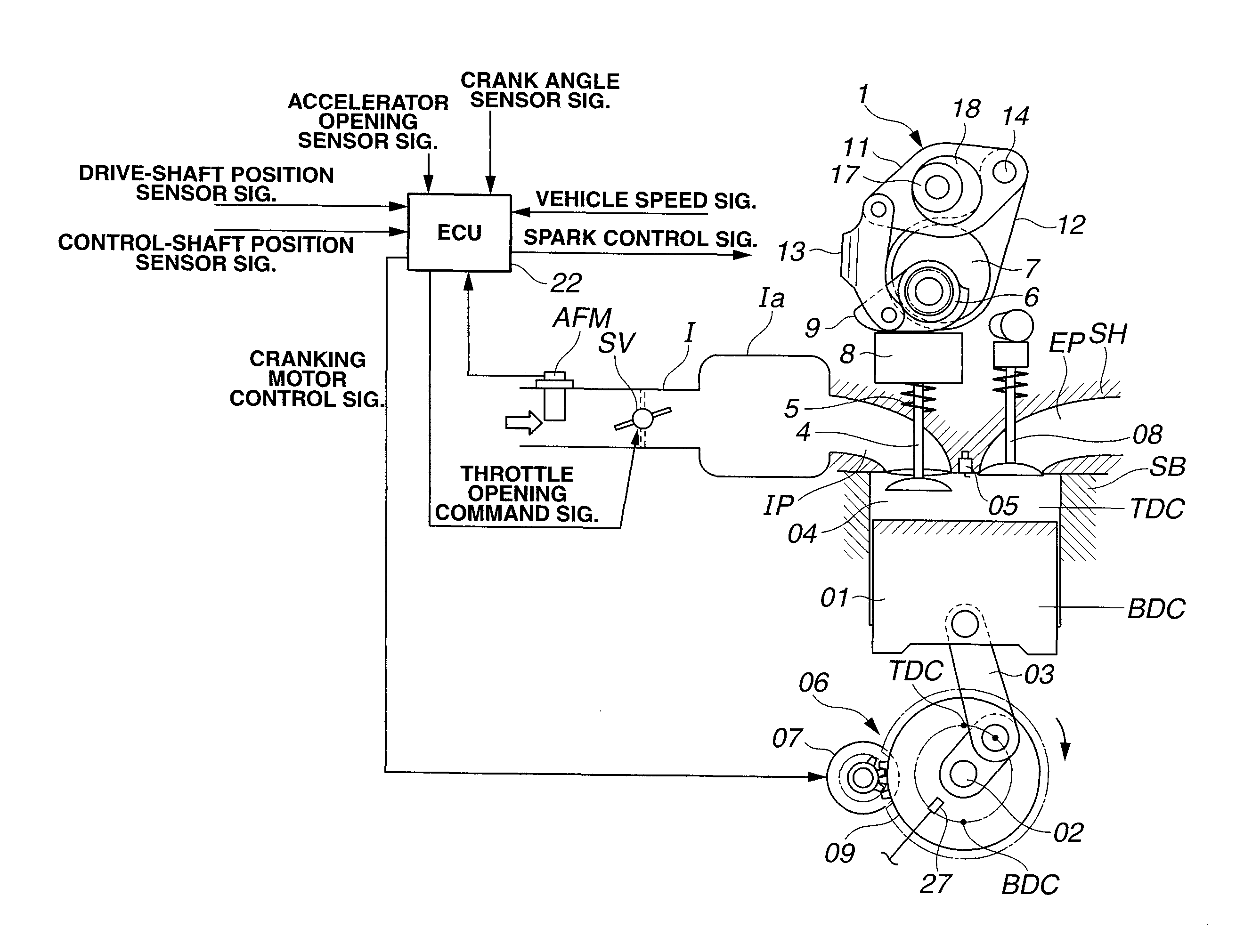
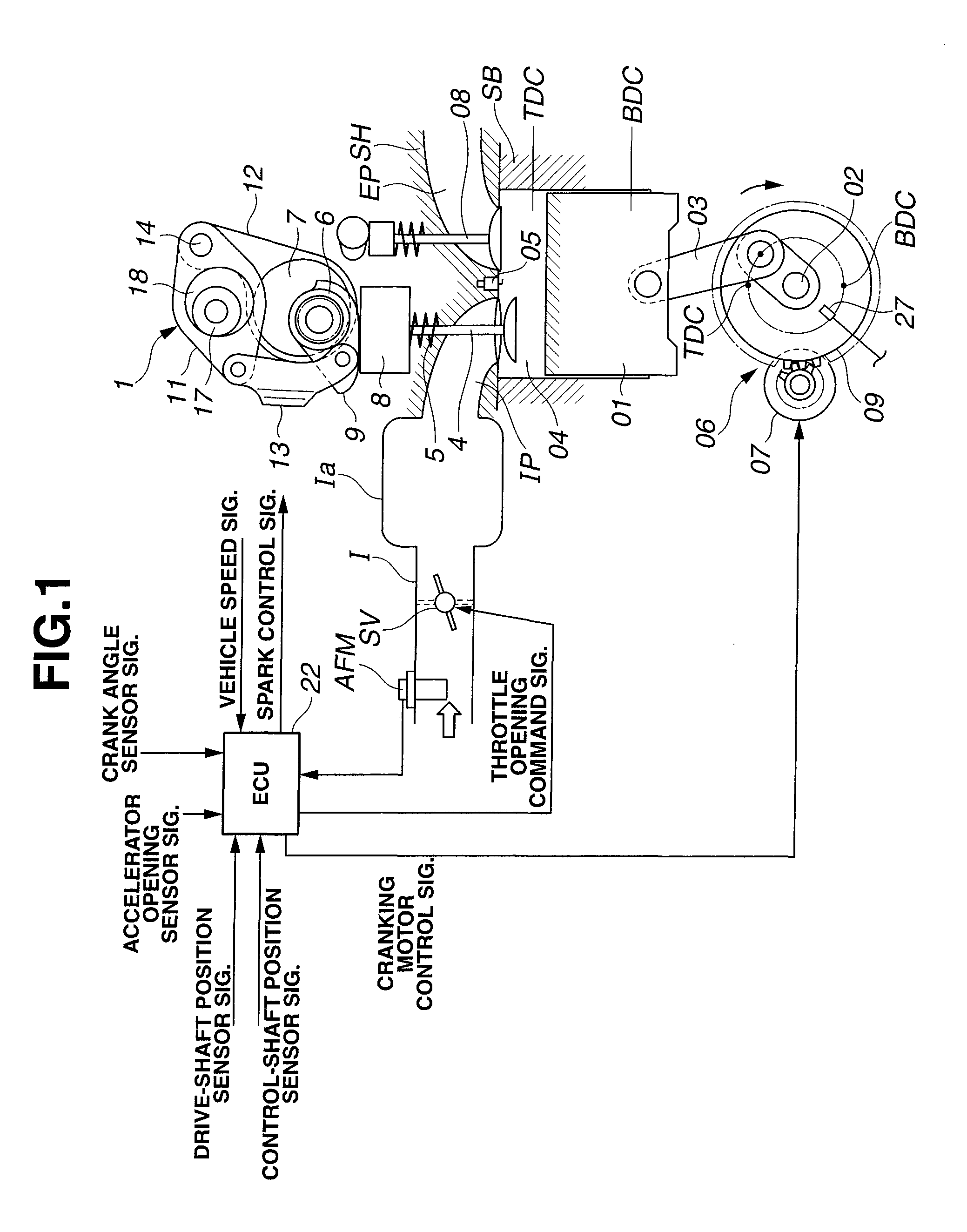
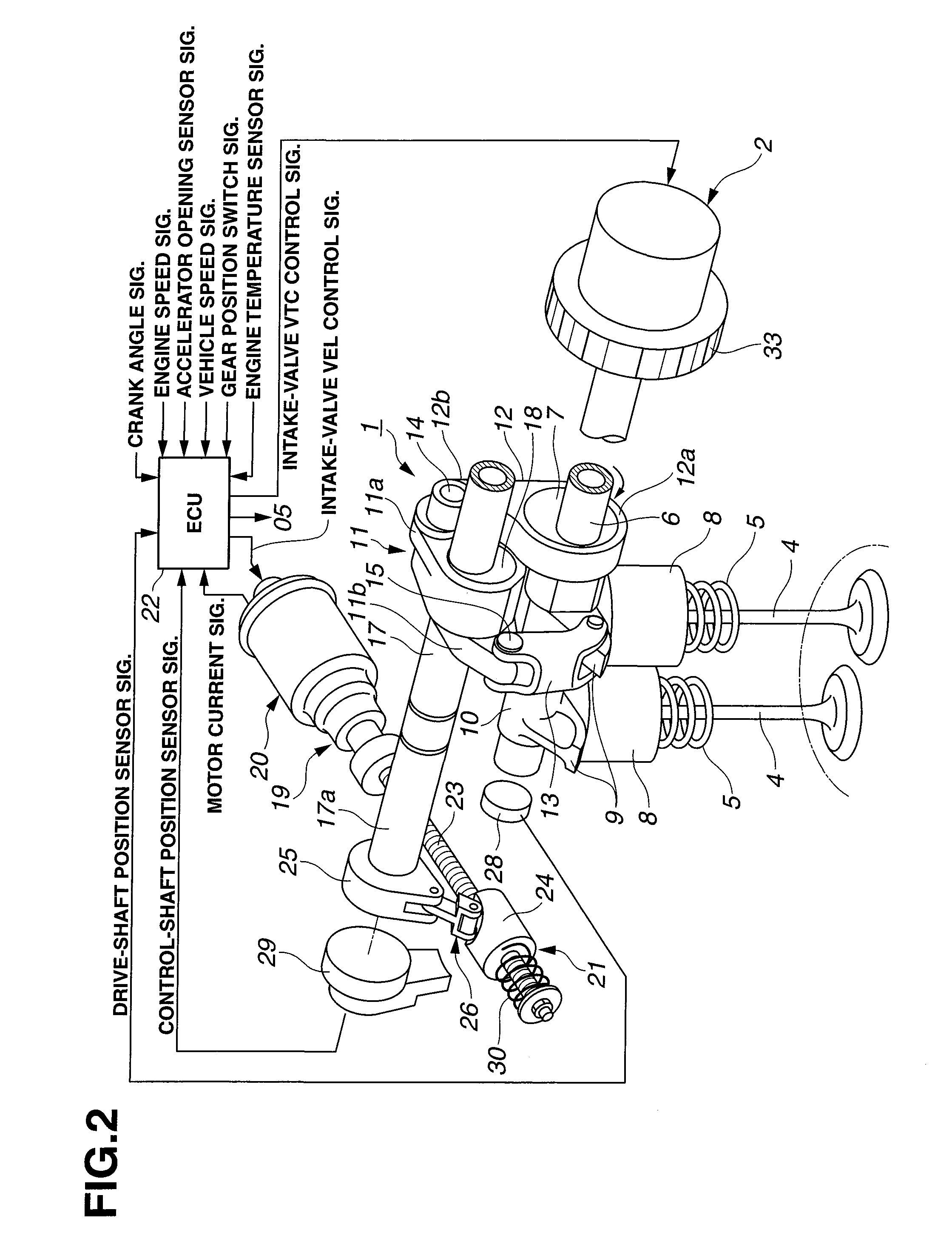
[0022]Referring now to the drawings, particularly to FIGS. 1-2, the engine control device of the first embodiment is exemplified in a four-cycle four-cylinder internal combustion gasoline engine having four valves per cylinder, namely two intake valves 4, 4 (see FIGS. 1-2) and two exhaust valves 08, 08 (see FIG. 1).

[0023]The construction of the multiple-cylinder internal combustion engine, to which the engine control device of the embodiment can be applied, is hereunder described in detail in reference to the system diagram of FIG. 1. Also, the engine control device of the embodiment can be applied to a hybrid vehicle (HV) employing an automatic engine stop-restart system capable of temporarily automatically stopping an internal combustion engine during idling without depending on a driver's will, in addition to an internal-combustion-engine equipped vehicle with a so-called idling-stop system that enables an idling-stop action. The engine of FIG. 1 is constructed by a cylinder bloc...

second embodiment

[0130]Referring now to FIGS. 11A-11B and 12, there is shown the engine control device of the second embodiment wherein the inventive concept is applied to an in-line two-cylinder internal combustion engine. The basic configurations of intake-valve VEL mechanism 1 and intake-valve VTC mechanism 2, both constructing the variable valve actuation device incorporated in the engine control system of the second embodiment, are the same as those of the first embodiment.

[0131]As can be seen from the characteristic diagrams of FIGS. 11A-11B, in the engine stopped state, intake-valve VEL mechanism 1 is held at a default position where the operating mode of each of intake valves 4, 4 is kept at its minimum working angle D1′ operating mode.

[0132]As clearly seen in FIGS. 11A-11B, there is a specific crankangle area α1′, in which intake valves 4, 4 of the two engine cylinders (#1 and #2 cylinders) are kept simultaneously in their closed states, near the TDC position of the #1 cylinder on compressi...


PUM


Abstract

In an internal combustion engine control device, when the engine stops, a variable valve actuation device is controlled to change an operating mode of each of intake valves to a specific state where an all-cylinder valve closed period, during which the intake valves of all engine cylinders are all kept in their non-lifted states, occurs, and a crank position change mechanism is controlled to change a crankshaft-rotation stopped position to a crankangle included within the all-cylinder valve closed period. When restarting the engine, the variable valve actuation device is controlled to bring the operating mode of each of the intake valves closer to an engine-start desired lift characteristic suited to an engine condition, prior to cranking action.

Description

TECHNICAL FIELD[0001]The present invention relates to a control device and a control system, capable of enhancing a restartability of a multi-cylinder internal combustion engine.BACKGROUND ART[0002]In recent years, there have been proposed and developed various multi-cylinder engine control devices configured to enhance a restartability. One such multi-cylinder internal combustion engine control device has been disclosed in Japanese Patent Provisional Publication No. 2003-56316 (hereinafter is referred to as “JP2003-056316”). Briefly speaking, as a variable valve actuation device, the engine control device disclosed in JP2003-056316 has a continuous variable valve event and lift control (VEL) mechanism capable of continuously varying a valve lift amount and a working angle of an intake valve and a variable phase control mechanism (a variable valve timing control (VTC) mechanism) capable of phase-shifting a central phase angle (e.g., a phase at a peak valve lift) of a valve lift char...

Claims


Application Information

Patent Timeline
IPC IPC(8): F01L1/34F01L9/10F01L9/22
CPCF01L1/3442F01L13/0021F01L13/0026Y02T10/18F02D13/0207F02D13/0265F01L2001/34453F01L2001/34483Y02T10/12
Inventor NAKAMURA, MAKOTO
Owner HITACHI AUTOMOTIVE SYST LTD
Why Eureka
Try Eureka