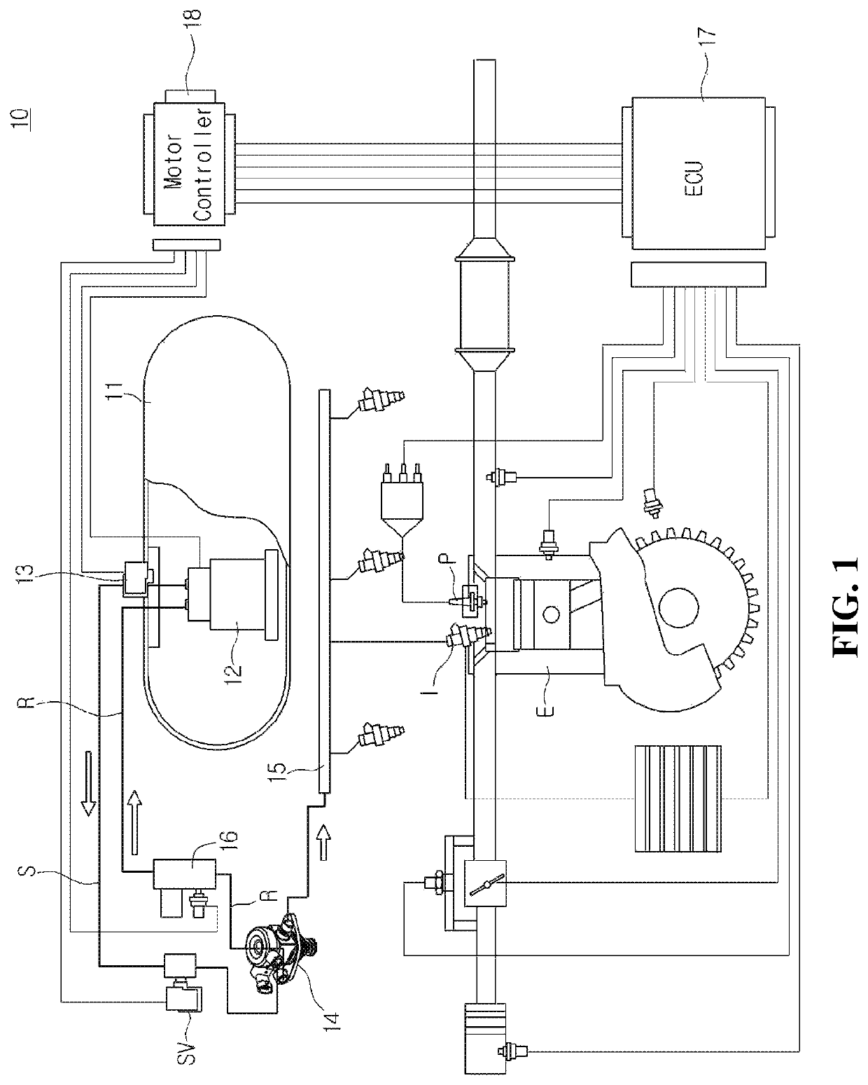
High pressure fuel pump and LPDI system with the same
a fuel pump and high-pressure technology, applied in the direction of fuel injecting pumps, machines/engines, electric control, etc., can solve the problems of deterioration of startability, difficult to improve startability, and wear of main components during driving, so as to improve startability, low lubrication, and easy elimination
- Summary
- Abstract
- Description
- Claims
- Application Information
AI Technical Summary
Benefits of technology
Problems solved by technology
Method used
Image

Examples
embodiment 1
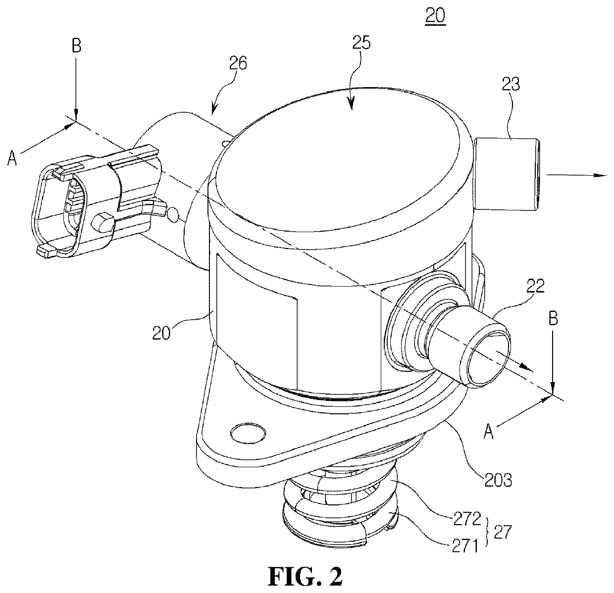
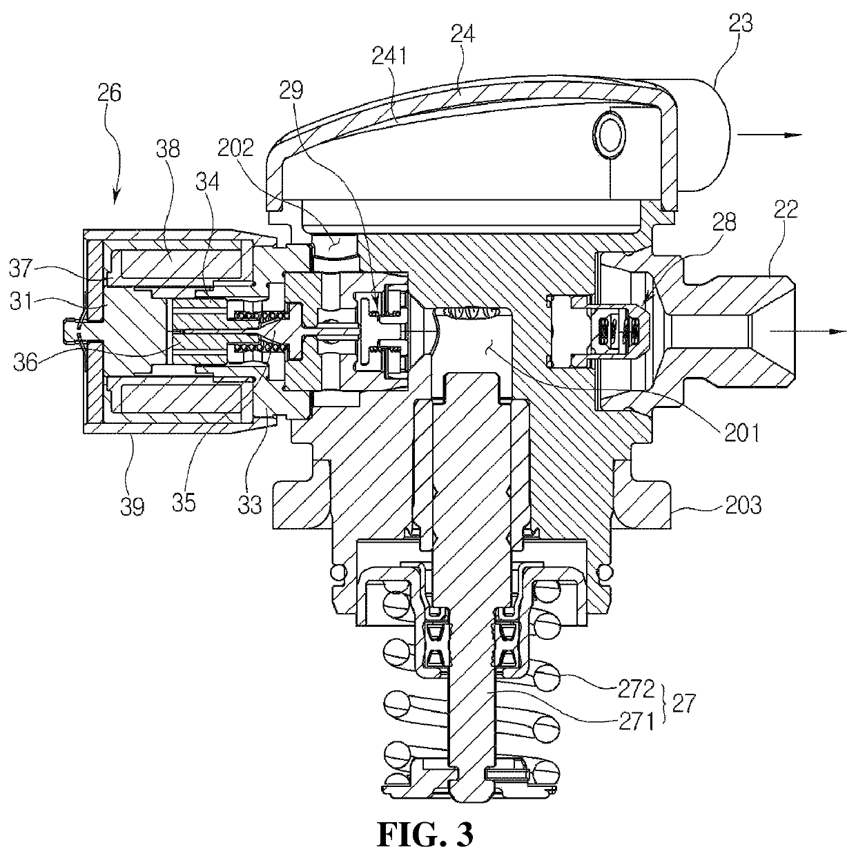
[0047]Next, the configuration of the high pressure fuel pump according to a first embodiment of the present invention will be described in detail with reference to FIGS. 2 to 4.
[0048]FIG. 2 is a perspective view showing a high pressure fuel pump according to a first embodiment of the present invention, FIG. 3 is a sectional view taken along line A-A′ of FIG. 2, and FIG. 4 is a sectional view taken along line B-B′ of FIG. 2.
[0049]As shown in FIGS. 2 to 4, the high pressure fuel pump 14 according to the first embodiment of the present invention may include a body 20 formed at a lateral side thereof with an intake port 21 and an exhaust port 22, and provided therein with a pressing device 27 configured to press a portion of fuel, which is supplied through the intake port 21, at a high pressure, a spill valve 26 coupled to one side of the body 20 to control a supply flow rate and exhaust pressure of the fuel, and a cover 24 coupled to an upper portion of the body 20 and having a recover...
embodiment 2
[0072]FIG. 5 is a partially enlarged sectional view of the high pressure fuel pump according to a second embodiment of the present invention.
[0073]As shown in FIG. 5, the high pressure fuel pump 14 according to the second embodiment of the present invention may have a configuration similar to the configuration of the high pressure fuel pump 20 according to the first embodiment described with reference to FIGS. 2 to 4, except that the recovery port 23 is formed on the upper surface of the cover 24.
[0074]Therefore, the cover 24 may have a dome shape in which a central portion of the upper surface of the cover 24 formed with the recovery port 23 is convex upward, and the upper surface of the cover 24 may be formed as an inclined surface 241 inclined downward in the outward direction from the center thereof.
[0075]As described above, according to the present invention, the cover has a dome shape, which is convex upward, to collect gaseous fuel inside the cover and recover the collected g...
embodiment 3
[0077]FIG. 6 is a sectional view of a cover and a damper portion of a high pressure fuel pump according to the third embodiment of the present invention, and FIG. 7 is an exploded perspective view of the cover and the damper portion shown in FIG. 6.
[0078]As shown in FIGS. 6 and 7, the high pressure fuel pump 14 according to the third embodiment of the present invention may include a damper portion 25 coupled to an upper portion of a body 20 to reduce pulsation of the fuel.
[0079]The cover 24 may be formed in a cylindrical shape with a lower surface opened so that a space for installing the damper portion 25 may be provided in the cover 24, and an edge portion of the cover 24 may be coupled to a plurality of coupling ribs 204 provided at an upper surface of the body 20.
[0080]The damper portion 25 may include a damper 251 having a plurality of valleys formed on an outer surface of the damper portion 25 and an upper guide 252 coupled to an upper portion of the damper 251 to fix the damp...
PUM
 Abstract
Description
Claims
Application Information
 - R&D
- Intellectual Property
- Life Sciences
- Materials
- Tech Scout
- Unparalleled Data Quality
- Higher Quality Content
- 60% Fewer Hallucinations
Browse by: Latest US Patents, China's latest patents, Technical Efficacy Thesaurus, Application Domain, Technology Topic, Popular Technical Reports.
© 2025 PatSnap. All rights reserved.Legal|Privacy policy|Modern Slavery Act Transparency Statement|Sitemap|About US| Contact US: help@patsnap.com