Electrophotographic apparatus

a technology of electrophotography and printing apparatus, which is applied in the direction of electrophotography process apparatus, thin material handling, instruments, etc., can solve the problems of limited miniaturization of the electrophotographic apparatus, limitation of double-face printing speed increase, and difficulty in miniaturization of the printer, so as to achieve a high printing speed

Active Publication Date: 2005-05-17
RICOH PRINTING SYST
View PDF13 Cites 13 Cited by
  • Summary
  • Abstract
  • Description
  • Claims
  • Application Information

AI Technical Summary

Benefits of technology

[0032]Accordingly, an object of the present invention is to provide an electrophotographic apparatus incorporating a double facing printing function, which can print at a high printing speed even during double face printing.
[0035]Conveying rollers for driving a recording medium which is inserted into the reversing conveying path and is then fed out, are provided on the body side of the electrophotographic apparatus so as to define the reversing conveying path as a mere hollow space, thereby it is possible to allow the structure of the opening door to be simple and thin.
[0038]Further, the provision of a mechanism for opening the casing upper part along the bypass conveying path facilitates maintenance in the casing upper part.

Problems solved by technology

However, since the tandem system color printer inevitably incorporates four image forming means, the miniaturization of the printer is difficult, that is, it has a size which is relatively larger than that of a repeated development system color printer.
Thus, the thickness of the opening door has to be about 70 mm at minimum since there is required a space for mounting conveying rollers to the reversing conveying path and the sheet refeeding means, in addition to the diameters of the curved guide portions, thereby there has been a limitation to miniaturization of the electrophotographic apparatus.
However, in order to carry out double face printing, since a sheet is conveyed through the main conveying path in a reverse direction, a printing sheet as a next page cannot be soon fed until the reversal is completed, there is a limitation to increasing of a printing speed of double face printing.

Method used


Image

  • Electrophotographic apparatus
  • Electrophotographic apparatus
  • Electrophotographic apparatus

Examples


embodiment 1

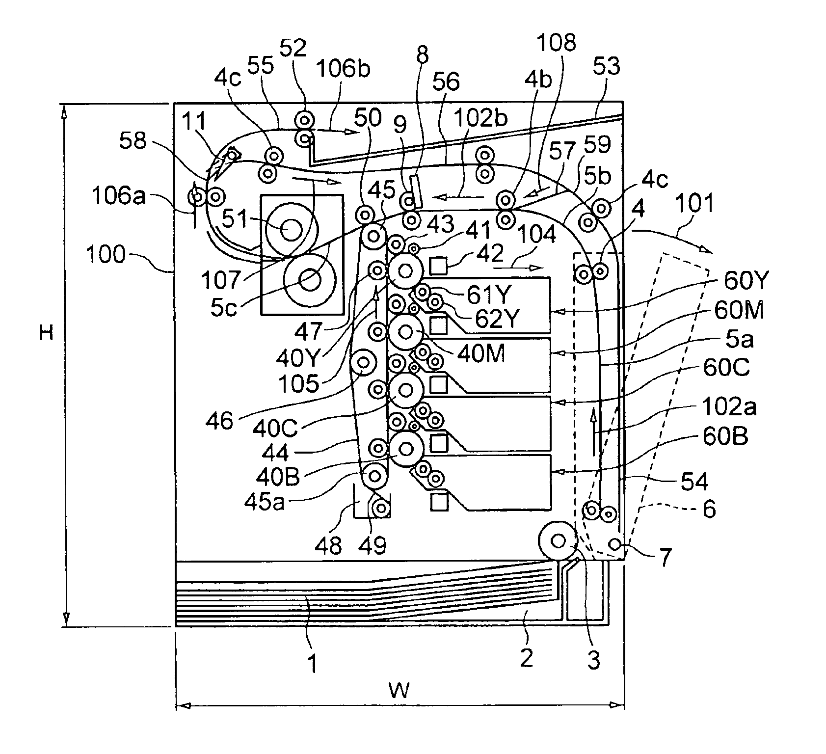
[0066]FIG. 1 shows an overall configuration of an electrophotographic apparatus incorporating a double face printing function according to the present invention.

[0067]The electrophotographic apparatus in the embodiment 1 is composed of a casing 100, a sheet cassette 2, a sheet separating means 3, a conveying means 4, a sheet conveying path 5, an opening door 6, a sheet position detecting means 8, a registering roller 9, four image forming means 70 for yellow Y, magenta M, cyan C and black K, an intermediate transfer belt 44, a drive roller 45, a driven roller 45a, a tension regulating roller 46, a transfer cleaning means 48, a second transfer means 50, a fusing means 51, a pair of sheet discharge rollers 52 and a sheet discharge tray 53.

[0068]The sheet cassette 2 is located in the bottom part of the casing 100 so as to be drawable in the front of the electrophotographic apparatus, in order to accommodate therein sheets 1. The sheet separating means 3 is incorporated in the front end...

embodiment 3

[0181]In an embodiment 3, the conveying length L1 extending from the second branch means 59 by way of the return conveying path 57 and the bypass conveying path 56, is given by:

L1×Pmax+Gap)

[0182]The sheet 1a which is fed out form the reversing conveying path 54 and is then conveyed in through the return conveying path 57 for printing the backside surface thereof after the printing has been already completed for the front surface thereof, passes by the next sheet 1b being overlapped with each other in a part of the conveying path from the second branch means 59 to the reversing conveying path 54.

[0183]Referring to FIG. 11, at the time point when the leading end of the sheet 1b having the front surface for which printing is completed reaches the second branch means 59, the trailing end of the sheet la which is fed out from the reversing conveying path 54 for printing the backside surface thereof, is still located in the reversing conveying path.

[0184]As shown in FIG. 12, during the pe...

embodiment 4

[0188]FIG. 13 is a view illustrating an embodiment 4 in which the return conveying path 57 from the second branch means 59 is formed in an S-like shape.

[0189]In the embodiment 4, the return conveying path 57 is curved into an S-like shape, and accordingly,

L1>(2×Pmax+Gap)

can be ensured, similar to the embodiment shown in FIG. 10. Thus, the sheet 1b which is conveyed through the bypass conveying path 56 and enters into the reversing conveying path 54 after a toner image is transferred onto and fixed on the front surface thereof, the sheet 1a which is fed out from the reversing conveying path in which the leading end thereof has been reversed into the trailing end, and enters into the bypass conveying path 5c in order to transfer and fix a toner image on the backside surface thereof, can be advanced in their respective directions without making contact with each other in the second branch means 59.

[0190]With the use of the above-mentioned configuration, the conveying path lengths L1, L...


PUM


Abstract

Provided is a small-sized electrophotographic apparatus having a double face printing function, which can print at a high speed even during double face printing. There are provided a recording medium conveying path 5 composed of a vertical conveying path 5a for upward conveying a sheet fed from a sheet cassette 2, outside of a developing means 60, a curved conveying path 5b and horizontal conveying path 5c for conveying the recording medium to a transfer means 50, a fusing means 51 located in the horizontal conveying path 5c, downstream of the transfer means 50, for fusing a toner image on the recording medium 2, a sheet discharge tray 53, a bypass conveying path for guiding a sheet to be subjected to double face printing, having one surface for which printing has been completed, a first branch means 58 for guiding the sheet to be subjected to double face printing from a conveying path for the sheet discharge tray 53 into the bypass conveying path 56, a reversing conveying path 54 for reversing the sheet conveyed in the bypass conveying path 54 during double face printing, a second branch means 59 for guiding the sheet which has been reversed in the reversing conveying path 54, into the horizontal conveying path 5c, and a return conveying path 57 for returning the sheet which has passed through the second branch means 59, into the return conveying path 57 for conveying the sheet to the horizontal conveying path.

Description

BACKGROUND OF THE INVENTION[0001]The present invention relates to an image forming apparatus such as a copying machine, a printer, a facsimile system which forms a color image with the use of electrophotography, and in particular, to an electrophotographic apparatus for forming a color image with the use of a plurality of color toners.[0002]With the electrophotography, a light beam is projected from an exposure means onto a photoconductive medium which is uniformly charged, so as to form a latent image corresponding to image data, and toner is stuck to the latent image on the photoconductive medium so as to develop the latent image. The thus obtained toner image is transferred onto and fixed on a recording medium.[0003]It is noted here that explanation will be hereinbelow made so as to use the recording medium as a sheet. However, the recording medium should not be limited to the sheet alone but there may be used a sheet-like recording medium made of any of various materials includi...

Claims


Application Information

Patent Timeline
Patent Type & Authority Patents(United States)
IPC IPC(8): G03G15/23G03G15/00B65H29/54B65H29/58B65H85/00G03G15/01
CPCG03G15/231G03G2215/0119
Inventor YAMASHITA, TAICHIROMIYASAKA, TORUYAGI, MASAHIROYAMADA, SHINTAROASUWA, KENJI
Owner RICOH PRINTING SYST
Why Eureka
Try Eureka