
Multi-axis vibration sensor with integral magnet

a multi-axis, magnet-based technology, applied in the field of vibration sensors, can solve the problems of inability to adapt to the use of portable condition monitoring devices, and inability to meet the needs of the user, so as to facilitate the proper orientation of the sensor and enhance the stability of the apparatus.

Inactive Publication Date: 2005-05-17
COMPUTATIONAL SYST
View PDF15 Cites 15 Cited by
  • Summary
  • Abstract
  • Description
  • Claims
  • Application Information

AI Technical Summary

Benefits of technology

[0008]The present invention eliminates the difficulties and disadvantages of the prior art by configuring a multi-axis vibration sensor to be placed in sensory contact with a machine. In accordance with a preferred embodiment of the invention, the inventive vibration sensor apparatus includes a housing having a first end and a second end. Disposed within the housing adjacent the first end and permanently built into or otherwise affixed thereto is a magnet for magnetically attaching the apparatus in a desired orientation to a mounting surface that transmits machine vibration. A multi-axis vibration sensor disposed within the housing adjacent the magnet senses vibration produced by the machine and outputs a plurality of sensor signals corresponding to the sensed vibration. The multi-axis vibration sensor, preferably a tri-axial sensor, is in rigid permanent relation to the magnet and electrically isolated therefrom. Also disposed within the housing is signal conditioning circuitry for conditioning the sensor signals. At the resonant frequency of the apparatus, the conditioned sensor signals preferably have a gain of less than 15 dB relative to the sensor's linear response range. A communication link adjacent the second end of the housing enables a peripheral device, such as a portable data collector, to access the sensor signals over a broad frequency band.
[0011]To enhance the stability of the apparatus when being attached to an uneven mounting surface, a plurality of feet are rigidly attached to the first end of the housing so that both feet contact the mounting surface when the apparatus is placed in sensory contact with the machine. The feet are preferably elongate and substantially parallel to one another. The mounting surface to which the sensor is magnetically attached may be an existing machine structure such as the machine's outer casing. Alternatively, a keyed mounting pad may be employed to facilitate proper orientation of the sensor when placed in sensory contact with the machine.

Problems solved by technology

However, such permanent mounting methods are less than desirable due to the labor and costs involved, and the use of attachment methods which do not permanently affix the accelerometer to the machine have historically proven to be disadvantageous as a result of poor sensor response.
When collecting data along multiple axes, the process is time consuming, inefficient, and susceptible to error as the sensor must be precisely aligned along each axis to ensure accuracy and repeatability.
Multi-axis vibration sensors have been available for a few years, but they have not been generally accepted as an alternative to single axis sensors for portable condition monitoring.
One reason for this is the difficulty in properly mounting a traditional multi-axis sensor to the machine.

Method used


Image

  • Multi-axis vibration sensor with integral magnet
  • Multi-axis vibration sensor with integral magnet
  • Multi-axis vibration sensor with integral magnet

Examples


Embodiment Construction

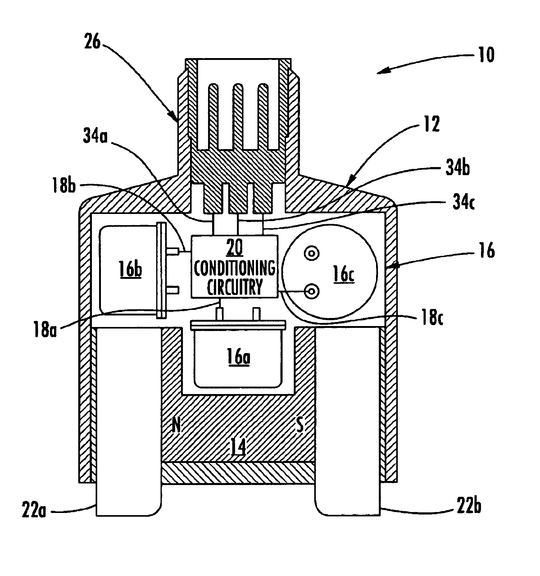
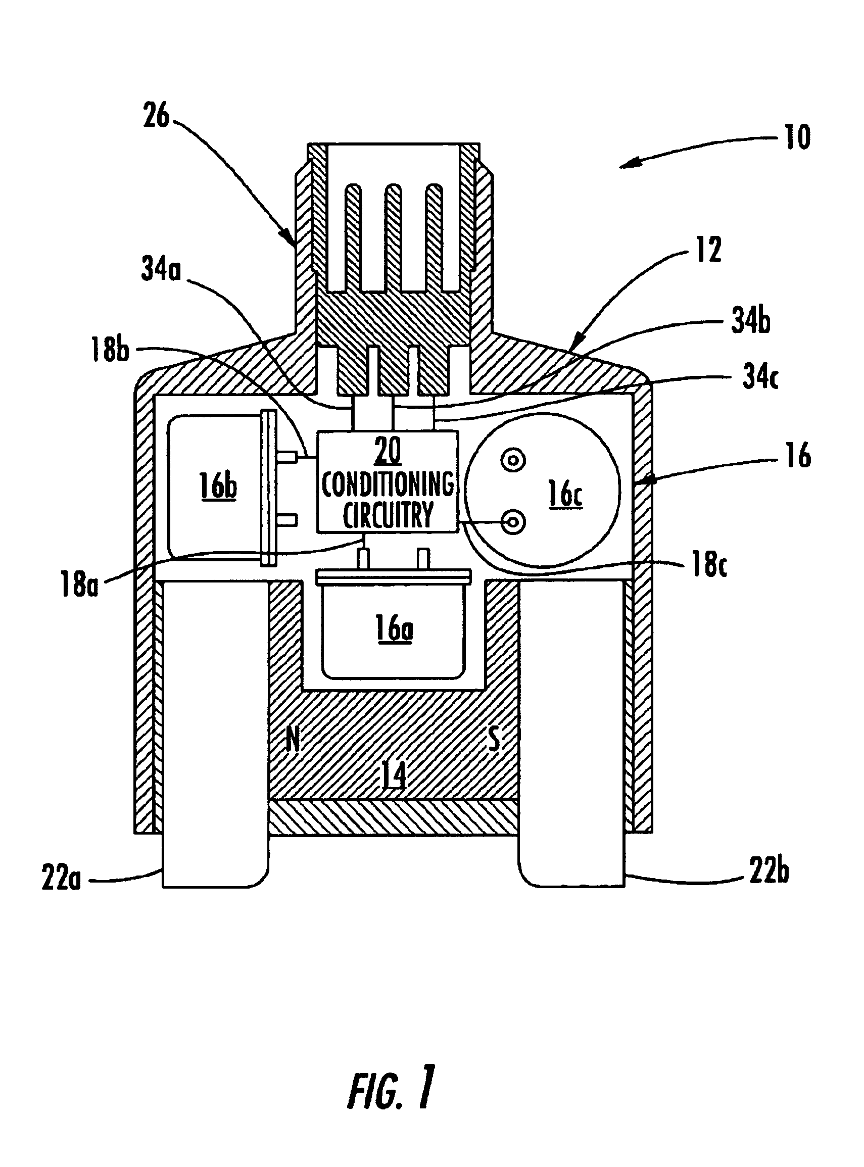
[0019]With reference now to the drawings in which like reference characters designate like or similar parts throughout the several views, FIG. 1 provides a cross-section view of a preferred embodiment of an integral magnet multi-axis accelerometer sensor in accordance with the invention. In the preferred embodiment shown in FIG. 1, the integral sensor 10 is placed in sensory contact with a machine by magnetically attaching the sensor 10 in a desired orientation to a mounting surface that transmits vibration produced by the machine. Preferably, the sensor 10 includes a housing and a magnet assembly including a magnet 14 used for removably attaching the sensor 10 to the mounting surface. The magnet 14 is preferably a permanent magnet fabricated from a neodymium compound (such as NdFeB) with a north pole (N) and a south pole (S) as shown. A plurality of vibration sensor modules 16a, 16b, and 16c (which collectively may be characterized as a multi-axis vibration sensor with a plurality ...


PUM


Abstract

A multi-axis vibration sensor with integral magnet optimizes sensor response in a non-permanently attachable package. In a preferred embodiment of the invention, the apparatus includes a housing having a magnet, a multi-axis vibration sensor for sensing vibration along multiple machine axes, and conditioning circuitry disposed within the housing. The magnet enables the apparatus to be placed in sensory contact with the machine. The vibration sensor senses machine vibration along multiple machine axes when the apparatus is in sensory contact with the machine, and the conditioning circuitry optimizes the frequency response of the vibration sensor by reducing the gain of the sensor output at resonance. The vibration sensor may be mounted directly to existing machine structure, such as the machine's outer casing. Two parallel feet facilitate stable mounting of the sensor curved surface. A keyed mounting pad may be employed to facilitate proper orientation of the sensor.

Description

[0001]This is a continuation-in-part of application Ser. No. 09 / 988,926 filed Nov. 19, 2001 and entitled “Integral Magnet Vibration Sensor”, which issued as U.S. Pat. No. 6,598,479.FIELD OF THE INVENTION[0002]The present invention relates generally to vibration sensors. More particularly, the present invention relates to a multi-axis vibration sensor module having an integral magnet for attaching the vibration sensor to a machine.BACKGROUND OF THE INVENTION[0003]Industrial and manufacturing facilities typically employ large electrically powered machines to provide the horsepower and motive forces needed for production. Proper operation of such machines is often essential to meeting production needs. To this end, production facilities often adopt predictive maintenance programs in which machines are periodically monitored to ensure proper operation. Many predictive maintenance programs employ vibration analysis as a way to assess the health of the machine. During vibration analysis, ...

Claims


Application Information

Patent Timeline
IPC IPC(8): G01H11/00G01H11/06
CPCG01H11/06
Inventor ROBINSON, JAMES C.PIETY, KENNETH R.PARDUE, BRADLEY D.
Owner COMPUTATIONAL SYST
Learn More