
Method and apparatus for polarization and wavelength insensitive pumping of solid state lasers

a solid state laser and wavelength-sensitive pumping technology, which is applied in the direction of excitation process/apparatus, laser details, active medium materials, etc., can solve the problems of tight control of the wavelength of the pump light, the deviation the change in size and divergence of the output beam of the amplifier, so as to achieve the effect of increasing the wavelength rang

Inactive Publication Date: 2005-05-10
NEWPORT CORP
View PDF9 Cites 18 Cited by
  • Summary
  • Abstract
  • Description
  • Claims
  • Application Information

AI Technical Summary

Benefits of technology

[0011]Another object of the present invention is to provide a diode-pumped laser and its methods of use, with a performance that is substantially independent of the polarization of the pump beam.
[0012]A further object of the present invention is to provide a diode-pumped laser and its methods of use, that has an increased range of wavelengths over which the absorption of the pump beam is constant.
[0014]In another embodiment of the present invention, a method of broadening an absorption band in a gain media selects a polarization state of a pump beam. The pump beam is directed through the gain media in a direction to increase a range of wavelengths over which an absorption of the pump beam is constant.
[0015]In another embodiment of the present invention, an optical system includes a gain media and a diode pump source. An optical coupler is positioned between the gain media and the diode pump source. The optical coupler produces a pump beam with a polarization state that increases a range of wavelengths over which an absorption of the pump beam is constant.

Problems solved by technology

For practical lasers, however, this often requires very tight control of the wavelength of the pump light, which implies a control mechanism to adjust the temperature of the pumping laser diodes.
Such a change in lensing will cause the output beam from an amplifier to change in size and divergence.
The problem is more severe in an oscillator, wherein the lensing can cause the cavity to become geometrically unstable.

Method used


Image

  • Method and apparatus for polarization and wavelength insensitive pumping of solid state lasers
  • Method and apparatus for polarization and wavelength insensitive pumping of solid state lasers
  • Method and apparatus for polarization and wavelength insensitive pumping of solid state lasers

Examples


Embodiment Construction

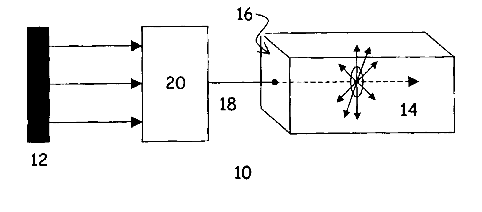
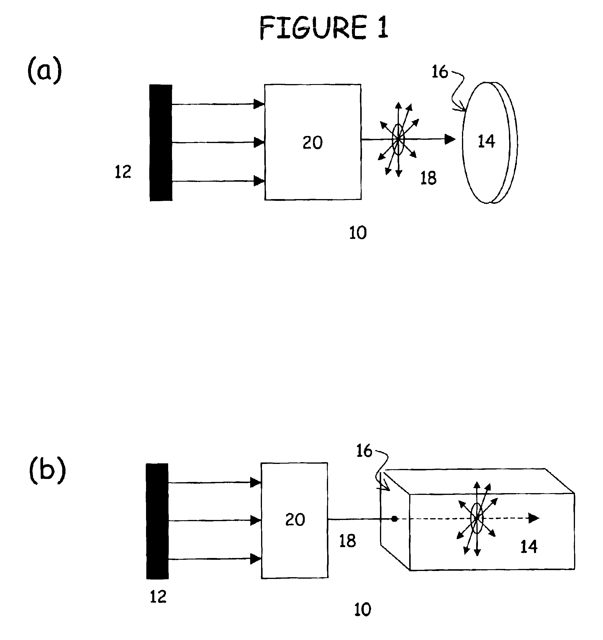
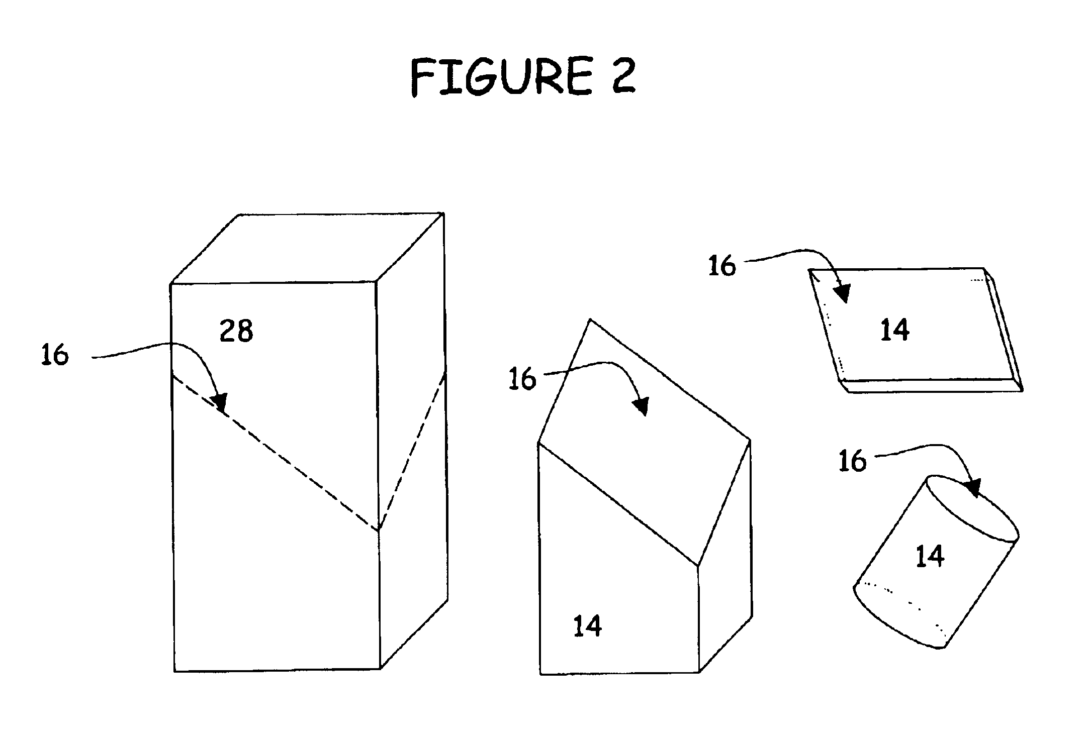
[0022]In one embodiment of the present invention, illustrated in FIGS. 1(a), 1(b) and 2, an optical system 10 includes a diode pump source 12 and a gain media 14. Gain media is made of a material with an anisotropic absorption and has a pump beam incidence surface 16 that is cut at an angle to produce substantially polarization-independent absorption of a pump beam 18.

[0023]Gain media 14 is cut in order to substantially equalize the absorption coefficient for the two principal polarizations of pump beam 18. In this manner, a change of the polarization state of pump beam 18 does not change the way that pump beam 18 is absorbed in gain media 14. Moreover, if the absorption spectra for the two principal polarizations of pump beam 18 cross in the wavelength range over which the pump source 12 is supposed to operate, a shift in wavelength that increases the absorption for one polarization, decreases the absorption for the other, will to first order not change the total absorption for pum...


PUM


Abstract

An optical system has a diode pump source, and a gain media made of a material with an anisotropic absorption. The gain media is cut at an angle to produce substantially polarization-independent absorption of a pump beam. An optical coupler is positioned between the diode pump source and the gain media. The optical coupler produces a pump beam that has substantially equal amounts of pump power along any two orthogonal axis that are orthogonal to the pump beam in the gain medium. The wavelength range allowed for the pump source is extended.

Description

CROSS-REFERENCE TO RELATED APPLICATIONS[0001]This application is related to U.S. patent application Ser. No. 10 / 233,140, and U.S. application Ser. No. 10 / 232,885 both of which are filed concurrently herewith.BACKGROUND OF THE INVENTION[0002]1. Field of the Invention[0003]This invention relates to end-pumped solid-state lasers and amplifiers, and more particularly to an optical system that has performance which is substantially independent of the polarization or wavelength of the pump beam.[0004]2. Description of Related Art[0005]Laser action generally requires a laser active material and means of pumping said medium. Of particular importance are the solid-state lasers, in which the gain medium is solid; typically a crystal or glass doped with laser-active ions, and the material is optically pumped with light of a suitable wavelength.[0006]Solid-state gain materials often show polarization dependent absorption of the pump light, which is particularly important for polarized pump beam...

Claims


Application Information

Patent Timeline
Patent Type & Authority Patents(United States)
IPC IPC(8): H01S3/0941H01S3/06H01S3/16
CPCH01S3/0941H01S3/0604H01S3/094073H01S3/1675H01S3/1618
Inventor SUTTER, DIRKKAFKA, JAMES D.
Owner NEWPORT CORP
Learn More