
Luminous container

a technology of luminous containers and containers, which is applied in the field of luminous containers, can solve the problems of difficult to achieve the optimal ratio of liquid agents for chemiluminescence, difficult to break capsules by external force or manual operation, and inability to have a large diameter of capsules, etc., to achieve the effect of enhancing portability, reducing storage space requirements, and maintaining the volume of chambers

Inactive Publication Date: 2005-05-10
LUMICA
View PDF3 Cites 13 Cited by
  • Summary
  • Abstract
  • Description
  • Claims
  • Application Information

AI Technical Summary

Benefits of technology

[0006]It is another object of the present invention to provide an improved luminous container capable of desirably arranging a capsule containing an agent for chemiluminescence.
[0008]At least a part of the housing may have flexibility, allowing manual deformation thereof for the capsule to be broken. Preferably, both of the inner and outer wall segments are made of a plastic material having flexibility and optical transparency. In view of the substances for chemiluminescence, an optimal material of the housing is polyethylene or polypropylene. It is not essential to provide optical transparency to the inner wall segment. When the inner wall segment is made of an opaque material, a desirable color of the material may be white. In this case, the chemiluminescence is reflected by the white inner wall segment and directed outside to provide enhanced brightness.
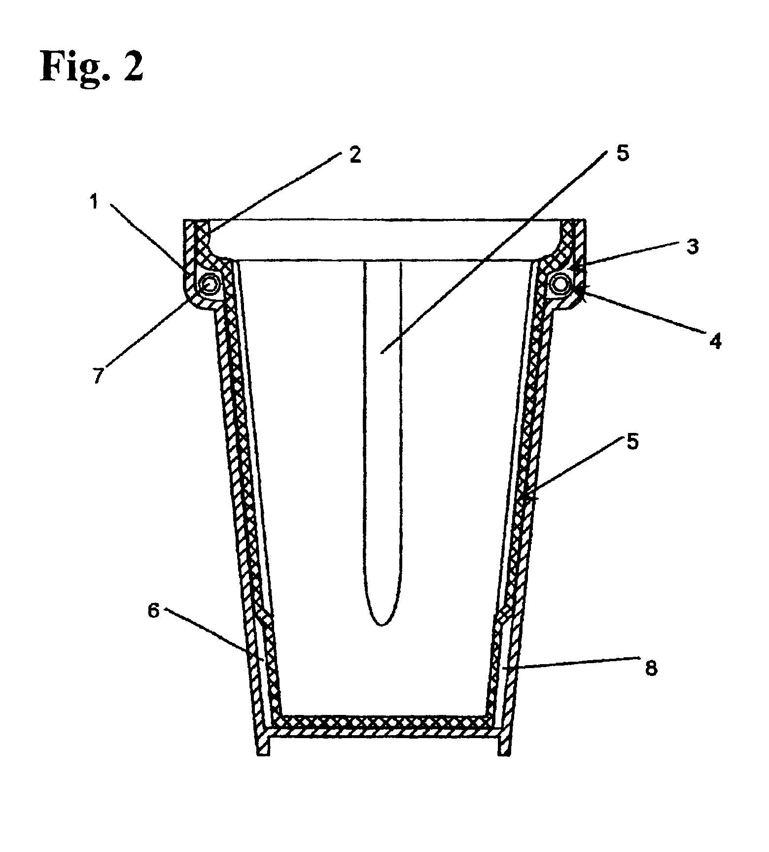
[0013]When the circular first chamber is arranged around the periphery of the housing, the periphery having a diameter of about φ80 mm (see FIG. 2), the entire length of the capsule is about 250 mm. In the conventional cup using a straight capsule, it is necessary to provide three capsules each having a length of 80 mm, and such straight capsules cannot be arranged in conformity with the periphery of the opening but housed only in the side portion of the housing away from the opening. Further, if a number of the straight capsules are arranged to satisfy the requirement of the ratio of the fluorescent material and oxidizing agent, it needs to repeatedly push the side portions of the housing in which the straight capsules are arranged, to obtain the chemiluminescence. On the other hand, in the present invention, the first chamber for receiving the capsule therein can be compactly arranged around and adjacent to periphery of the opening of the housing. Thus, the capsule can be readily broken by deforming the opening.
[0016]The integral portion may be provided by partially bonding the respective bottom portions and / or the side portions of the inner and outer wall segments by means of ultrasonic bonding or the like to prevent the aforementioned deformation of the housing.
[0018]Further, by taking advantage of the first chamber capablity of being compactly arranged around the periphery of the opening of the housing, the wall may have a configuration allowing two of the containers identical to each other to be fitted with one inside the other by inserting the outer wall segment of one of the containers into the opening and storage space of the other container. This reduces storage space requirements and enhances portability of the containers.

Problems solved by technology

This causes the following disadvantages in addition to the restriction on the location of the capsule chamber for receiving the capsules therein.
Firstly, in the cup having the capsules placed in the bottom portion of the housing, the small space of the bottom portion sets a limit on the number of the capsules, and thereby the capsules cannot have a large diameter.
As a result, the limited volume of the liquid agent in the capsules makes it difficult to achieve an optimum ratio of the two liquid agents for chemiluminescence.
Further, since the capsules are housed in the bottom portions, it is more difficult to break the capsules by external force or manual operation.
If the capsules are successfully broken, the agents in the capsules are not adequately mixed with the other agents because the other agents are in the side portions of the housings.
Secondly, in a cup having the capsules vertically in the side portion of the housing, the capsule chamber creates a protrusion extending outward or inward in the side portion.
This deteriorates the aesthetic configuration of the cup.
The increased thickness of the side portion makes it difficult to stack the plurality of cups by fitting one within another, resulting in increased storage space requirements and degraded portability.
This provides strong lights only in certain portions and the entire cup cannot give off light evenly.

Method used


Image

  • Luminous container
  • Luminous container
  • Luminous container

Examples


Embodiment Construction

[0031]Various embodiments of the present invention will now be described with reference to the drawings.

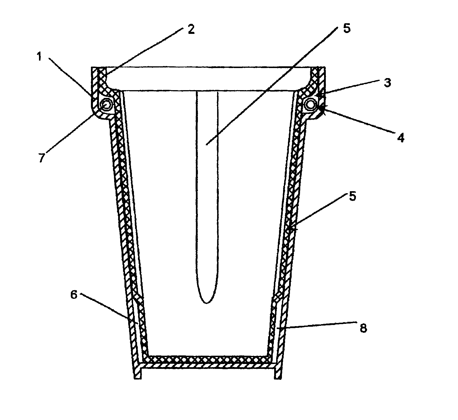
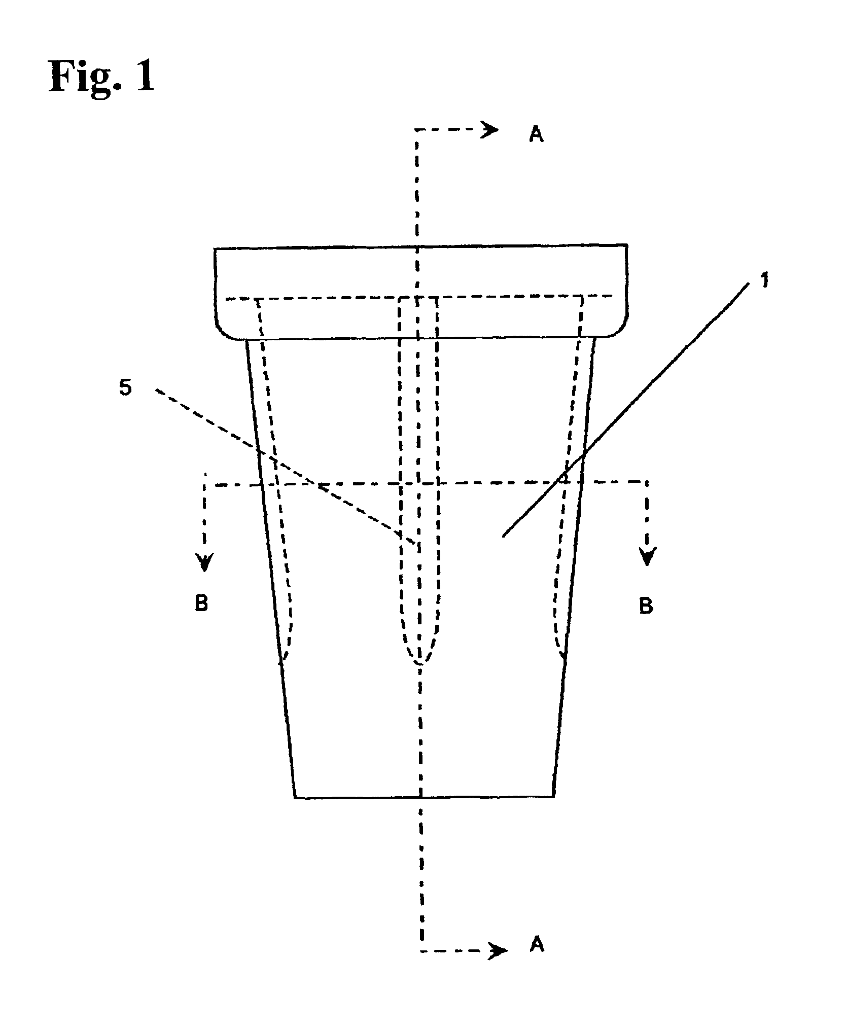
[0032]FIGS. 1 to 3 show a cup as a container according to a first embodiment of the present invention. The cup comprises a housing including an opening, and a wall defining the opening and a storage space contiguous with the opening. The wall includes a cup-shaped outer case 1 as an outer wall segment. As best shown in FIG. 2, the outer case 1 has a relatively larger opening of 80 mm in diameter, and includes a vertical flange portion surrounding the opening and having a height of 18 mm.

[0033]The wall further includes an inner case 2, having a shape similar to the outer case, as an inner wall segment. The inner case 2 has a vertical flange portion surrounding its opening as the opening of the housing. The vertical flange has a height of 10 mm, less than that of the flange portion of the outer case, to provide a first doughnut-shaped chamber 3 in parallel with or around the periphe...


PUM


Abstract

The present invention provides a container including a housing with an opening and a wall. The wall includes an inner case 2 fitting into an outer case 1 while leaving a given distance therebetween to form first and second chambers. The first chamber 3 is located around the periphery of the opening of the housing. Further, a capsule 4 is housed in the first chamber 3. First and second substances capable of chemiluminescence upon reaction with one another are contained in the capsule 4 and in the second chamber 6, respectively.

Description

FIELD OF THE INVENTION[0001]The present invention relates to a luminous container usable for various articles such as a cup, candy box or vase.BACKGROUND OF THE INVENTION[0002]Some luminous cups have heretofore been known. For instance, one conventional luminous cup comprises a housing, a capsule placed in a space between the inner and outer bottom walls of the housing, and two different liquid agents filled, respectively, in the space and in the capsule. The liquid agents are capable of chemiluminescence upon reaction with one another. When the capsule is broken by a user, the liquid agents are mixed together to cause chemiluminescence, and the generated light projects out through the outer wall. By virtue of the light, the user can easily handle the cup, even at night, and enjoy the illumination and other effects. In another conventional luminous cup, a plurality of the capsules is arranged vertically in a space between the inner and outer sidewalls of the housing. However, the ca...

Claims


Application Information

Patent Timeline
IPC IPC(8): A47G19/22A47G7/06A47G7/00B65D1/22B65D1/26F21K2/00F21K2/06A47G19/02
CPCA47G7/06A47G19/2227F21K2/06B65D1/265B65D2203/00A47G2019/2238
Inventor HARADA, SHIROFUJITA, MASAHIKOSHINOHARA, TOSHIFUMI
Owner LUMICA
Learn More