
Seat rail structure

Inactive Publication Date: 2005-05-10
HONDA MOTOR CO LTD
View PDF6 Cites 28 Cited by
  • Summary
  • Abstract
  • Description
  • Claims
  • Application Information

AI Technical Summary

Benefits of technology

[0008]Accordingly, it is an object of the present invention to provide a technique which can facilitate manufacturing of a seat rail.
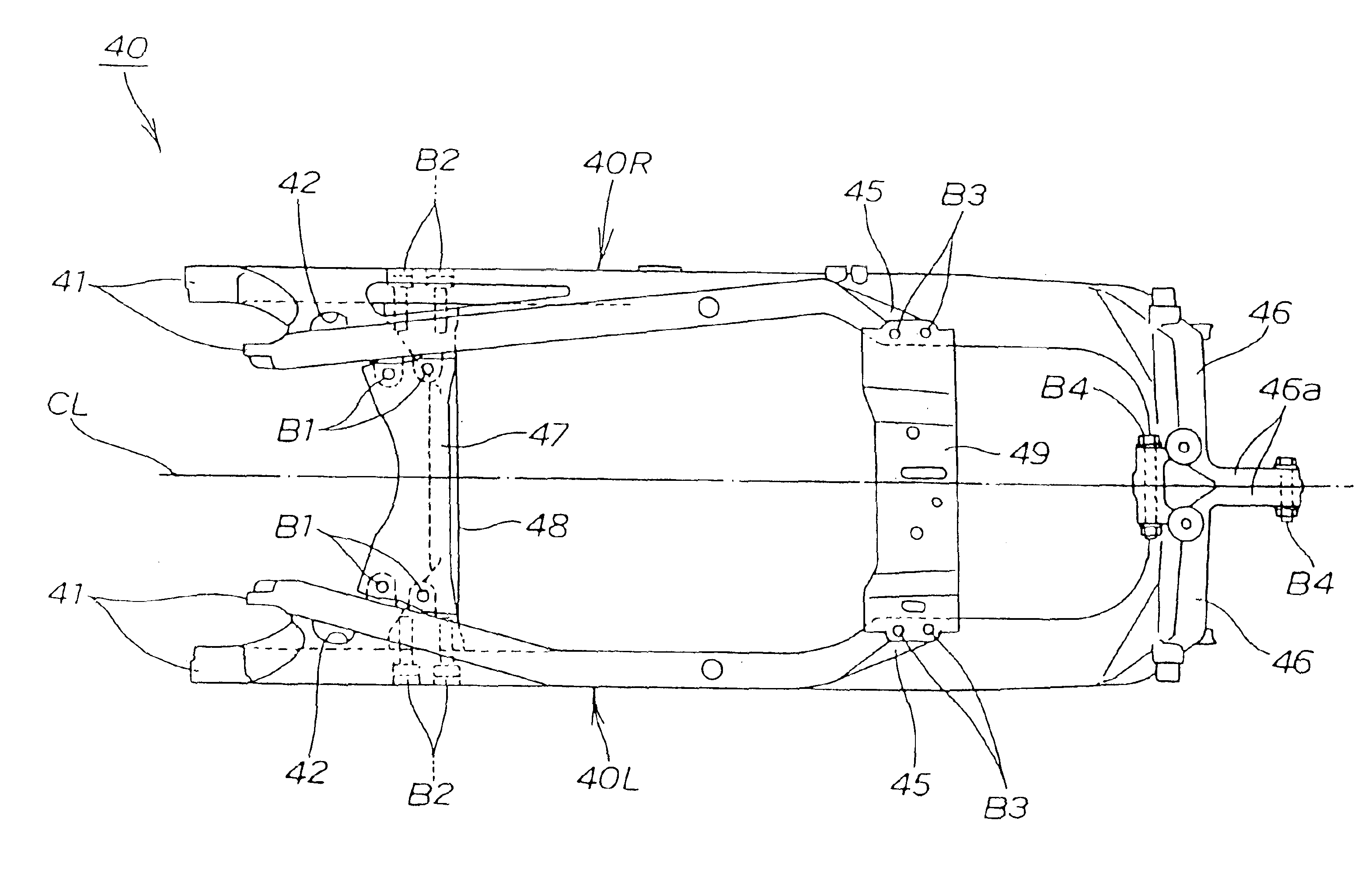
[0010]Since the seat engaging member is formed on the cross member, it is no longer necessary to form the seat engaging member on the seat rail. Accordingly, the shape of the seat rail can be simplified and hence, molding by casting is facilitated. By forming the seat rail as a cast product, a left-and-right two-split seat rail can be easily manufactured.
[0011]On the other hand, the cross member is provided with only the seat engaging member and hence, the shape of the cross member can be simplified. Accordingly, the cross member can be formed of a press molded product having a simple shape and hence, the cross member can be easily manufactured.
[0012]In this manner, the left-and-right two-split seat rail and the cross member which can be easily manufactured can be combined and integrally formed using fastening members and hence, the seat rail can be produced more easily.
[0014]Since the left and right seat rails can be molded using a split mold which can be respectively divided in the vehicle body width direction, molding can be performed more easily.
[0016]Since the heat shielding plate for engine exhaust muffler and the seat mounting member are fastened to the seat rail using bolts in an overlapping manner and the heat shielding plate for engine exhaust muffler and the cross member are fastened to the seat rail using bolts in an overlapping manner, the heat shielding plate, the seat mounting member and the cross member can be assembled to the seat rail with a simple operation whereby the assembling operability is enhanced.

Problems solved by technology

Hence, it is difficult to manufacture the seat rail.

Method used


Image

  • Seat rail structure
  • Seat rail structure
  • Seat rail structure

Examples


Embodiment Construction

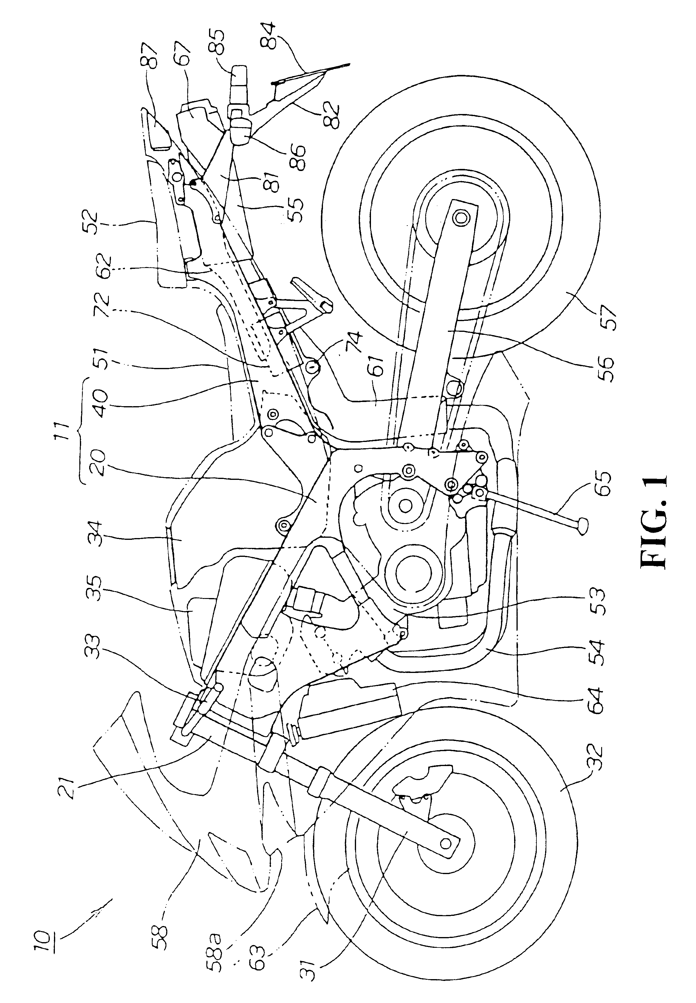
[0030]In the attached drawings, “front”, “rear”, “left”, “right”, “up” and “down” are directions as viewed from a driver.

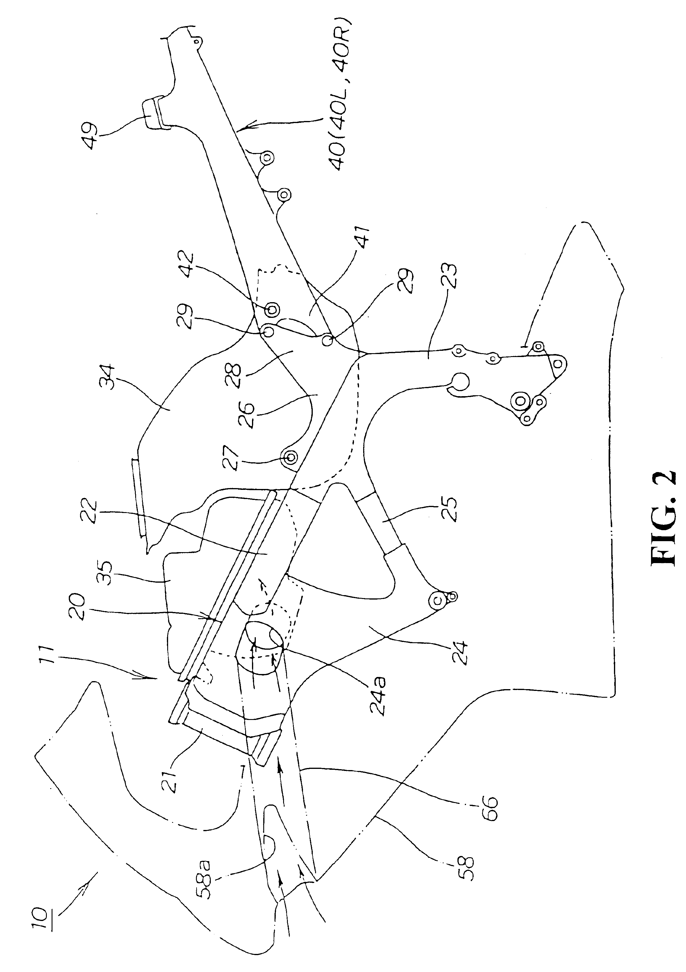
[0031]FIG. 1 is a left side view of a motorcycle according to the invention. The motorcycle 10 includes, as main constitutional members thereof, a cradle-type vehicle body frame 20, a front fork 31 which is mounted on a head pipe 21 of the vehicle body frame 20, a front wheel 32 which is mounted on the front fork 31, a handle 33 which is connected to the front fork 31, a fuel tank 34 and an air chamber 35 which are mounted on an upper portion of the vehicle body frame 20, a seat rail 40 which extends rearward from the vehicle body frame 20, and a front seat 51 and a rear seat 52 which are mounted on the seat rail 40. A four cycle engine 53 is arranged in the inside of a cradle space of the vehicle body frame 20, a muffler 55 is connected to an exhaust port of the engine 53 by way of an exhaust pipe 54, a swing arm 56 is suspended by a rear cushion (not shown in th...


PUM


Abstract

A seat rail extending rearwardly from a vehicle body frame to support a seat. The seat rail is formed of a left-and-right two-split cast product having a substantially flat upper surface and, at the same time, includes cross members. These cross members can be mounted later using bolts. The seat can be arranged above the seat rail and the cross members and, at the same time, a seat engaging member which engages the seat with the cross member can be formed on the cross member. The seat rail is constituted of the left and right seat rails which are divided with respect to a vehicle width center. This seat rail structure provides for simple manufacture and assembly.

Description

CROSS-REFERENCE TO RELATED APPLICATION[0001]The present application claims priority under 35 U.S.C. §119 to Japanese Patent Application No. 2002-264056, filed Sep. 10, 2002, the entire contents of which are hereby incorporated by reference.BACKGROUND OF THE INVENTION[0002]1. Field of the Invention[0003]The present invention relates to an improved technique of a seat rail structure of a motorcycle.[0004]2. Description of Background Art[0005]In a motorcycle, there has been known the seat rail structure which extends rearward from a vehicle body frame to support a seat (for example, see patent literature of JP-B-7-64302 (page 2 to 3, FIG. 1).[0006]According to the JP-B-7-64302, in the conventional seat rail structure, a seat rail is mounted on a rear portion of a vehicle body frame by fastening using bolts.[0007]The conventional seat rail adopts a three-dimensional skeletal structural body which spans left and right rail portions with a plurality of cross members, and is formed of any ...

Claims


Application Information

Patent Timeline
IPC IPC(8): B62M7/02B62M7/00B62K11/04B62J1/12B62K19/30
CPCB62K19/30B62K11/04
Inventor KURAYOSHI, YOSHIYUKIHIRAYANAGI, SATOSHIWATANABE, SHIN
Owner HONDA MOTOR CO LTD
Learn More