
Long-distance blast banger

a long-distance, banger technology, applied in the field of blast bangers, can solve the problems of large shock force, achieve the effect of reducing wind resistance coefficient, avoiding formation of large fragments, and increasing the flight range of the banger assembly

Inactive Publication Date: 2005-05-10
204TH ARSENAL MATERIEL PROD CENT THE ARMEMENT BUREAU M N D +1
View PDF8 Cites 17 Cited by
  • Summary
  • Abstract
  • Description
  • Claims
  • Application Information

AI Technical Summary

Benefits of technology

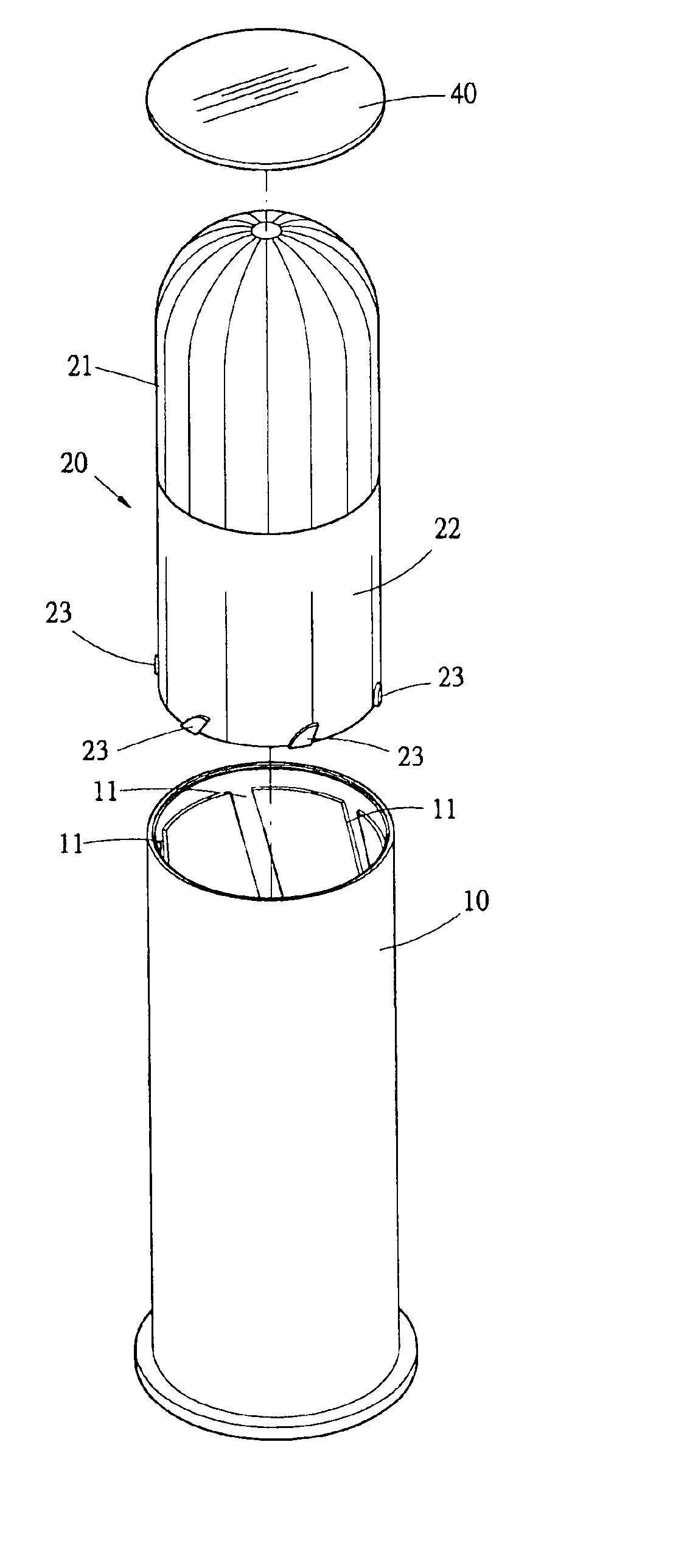
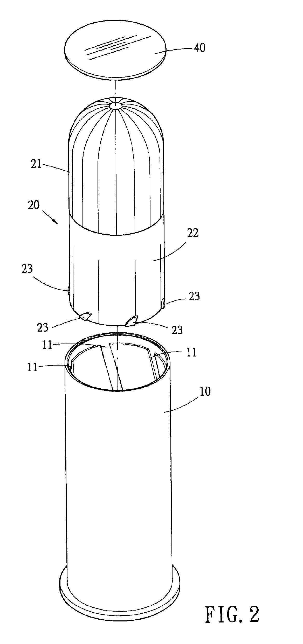
[0007]A long-distance blast banger of the present invention comprises a cartridge loaded with a banger assembly made of plastic material, wherein the banger assembly includes a sound explosives cup loaded with a sound explosives formulation, and a delay cup loaded with a delay formulation. At least two helical grooves extending from a bottom to a top of the cartridge are defined on an inner wall of the cartridge, and ear attachments are configured on a base of an outer wall of the balst banger so as to correspond with the helical grooves, thereby engendering a spinning stability effect during flight time of the banger assembly, and reducing wind resistance coefficient, while further coordinating with a propellent action of the delay formulation to actualize a significant increase in flight range of the banger assembly.
[0009]In addition, the sound explosives cup is loaded with a sound explosives formulation having components including perchloryl potassium, magnesium powder and aluminum powder. A sufficient sound value is acquired through appropriate compactness of the sound explosives cup, and therefrom realizes uniform shattering of the cup into small fragments that are insufficient to cause injury. The long-distance blast banger thus achieves a long flight range, and generates a large shock force, while averting damage or injury to aircraft or personnel.

Problems solved by technology

The long-distance blast banger thus achieves a long flight range, and generates a large shock force, while averting damage or injury to aircraft or personnel.

Method used


Image

  • Long-distance blast banger
  • Long-distance blast banger
  • Long-distance blast banger

Examples


Embodiment Construction

[0014]In order to clearly describe structure, configuration and integral method of employment of the present invention, a description accompanied by drawings is disclosed hereinafter:

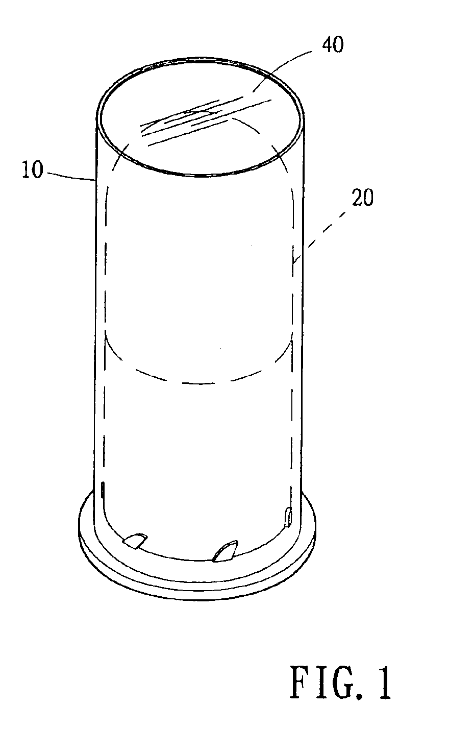
[0015]Referring to FIG. 1, which depicts a basic structure of a long-distance blast banger of the present invention comprising a cartridge 10 loaded with a blast banger 20 made up from plastic material. A seal lamella 40 further seals the blast banger 20 within the cartridge 10.

[0016]With reference to FIGS. 2 and 3, which show the blast banger 20 encompassing a sound explosives cup 21 loaded with a sound explosives agent, and a delay cup 22 loaded with a delay formulation. Furthermore, a percussion primer 30 is configured in a bottom of the cartridge 10, which is utilized to ignite the delay explosives agent. At least two helical grooves 11 extending from the bottom to a top of the cartridge 10 are defined on an inner wall of the cartridge 10, and ear attachments 23 are configured on a base of an outer ...


PUM


Abstract

A long-distance blast banger including a cartridge loaded with a blast banger made up from plastic material. The blast banger encompasses a sound explosives cup and a delay cup. The sound explosives cup is loaded with a sound explosives agent having components including perchloryl potassium, magnesium powder and aluminum powder. A sufficient sound value is acquired through appropriate compacting of the sound explosives cup, and therefrom realizes uniform shattering of the cup into small fragments that are insufficient to cause injury. Furthermore, at least two helical grooves extending from a bottom to a top of the cartridge are defined on an inner wall thereof, and ear attachments are configured on a base of an outer wall of the blast banger so as to correspond with the helical grooves, thereby engendering a spinning stability effect during flight time of the blast banger, reducing wind resistance, and thus increasing flight range.

Description

BACKGROUND OF THE INVENTION[0001](a) Field of the Invention[0002]The present invention relates to a blast banger, and more particularly to structure of the long-distance blast banger and explosives formulation art. Furthermore, the long-distance blast banger of the present invention effectuates a high-decibel explosive sound, which will not endanger aircraft or personnel.[0003](b) Description of the Prior Art[0004]Accordingly, no matter whether public or military airfields, in order to avoid noise generated from aircraft taking off and landing affecting residents, majority of airports are located at some considerable distance from residential districts. Furthermore, taking into account extensive grassland and remoteness from interference of a multitude of people of hinterland of the airport itself (and thereby suitable for sustaining flying insects) makes the airport an ideal location for birds to flock together and forage for food, as well as attracting wild dogs and rodents includ...

Claims


Application Information

Patent Timeline
IPC IPC(8): F41A21/18F42B4/16F42B4/00F42B4/02F42B4/04F42B5/26F42B8/00F42B8/02F42B8/14F42B5/00F42B5/02F41A21/00F42B10/38F42B10/00F42B10/26A01M29/20
CPCF41A21/18F42B4/02F42B4/04F42B4/16F42B5/02F42B12/20F42B8/02F42B8/14F42B10/26F42B10/38F42B5/26
Inventor LIAW, JOEYFAN, KUEI-FUCHANG, SHI-XINGCHEN, SHU-FANG
Owner 204TH ARSENAL MATERIEL PROD CENT THE ARMEMENT BUREAU M N D
Learn More