
Clean-in-place automated food or beverage dispenser

a food or beverage dispenser and automatic technology, applied in the direction of cleaning using liquids, instruments, milk treatment, etc., can solve the problems of milk quickly spoilage, other food dispensers may easily be subjected to bacterial contamination and growth, and serious sanitary problems may occur

Inactive Publication Date: 2005-05-10
NESTEC SA
View PDF21 Cites 55 Cited by
  • Summary
  • Abstract
  • Description
  • Claims
  • Application Information

AI Technical Summary

Benefits of technology

[0013]The invention also relates to a clean-in-place system for an automated dispenser comprising a product flowpath configured to supply a milk based fluid. This system includes at least one source of rinsing, cleaning or sanitizing fluid, a buffer reservoir configured to initially retain the rinsing, cleaning or sanitizing fluid, a clean-in-place flowpath assembly configured in a loop to recirculate at a certain velocity the rins...

Problems solved by technology

Serious sanitary problems may occur with microbiologically sensitive products such as low acid starting components that can enter into the composition of an on-demand prepared beverage.
Other food dispenser may easily be subjected to bacterial contamination and growth such as soft ice cream serving machines.
Milk can rapidly spoil when it comes into contact with contaminated moisture, dust, fluid, etc., and thus proper handling and dispensing of such a product can be challenging.
If done manually, this process is very laborious, time consuming and expensive in manpower.
Furthermore, neglect or error in the cleaning process may not only affect the quality of the beverage but also lead to serious hygienic hazards.
However, using an ozone generator with this system has a number of disadvantages.
Ozone generators tend to be expensive and bulky.
Ozone can damage the lungs when inhaled.
As a result, safety considerations arise due to the use of high voltage, and relatively high electrical power consumption occurs.
Moreover, since ozone is very reactive, it cannot be stored in water, and must be generated on demand by the system.
This clean-in-place system is cumbersome and complicated due to the number of sanitizing / rinsing lines and the same number of sanitizing / rinsing sources corresponding to those lines.
Furthermore, the system is very much sanitizer consuming in the sense that the sanitizer flows through the dispenser and is evacuated through the dispensing valve.
However, in order to be effective, soaking must be maintained during several hours which means that a full cleaning protocol can only be carried out overnight.

Method used


Image

  • Clean-in-place automated food or beverage dispenser
  • Clean-in-place automated food or beverage dispenser
  • Clean-in-place automated food or beverage dispenser

Examples


examples

[0101]The following examples are provided to illustrate preferred operating modes of the automated food dispenser in accordance with the invention. Each of these operating modes is for exemplary purposes only, and in no way are intended to limit the scope of the invention.

example i

New Reservoir Connection

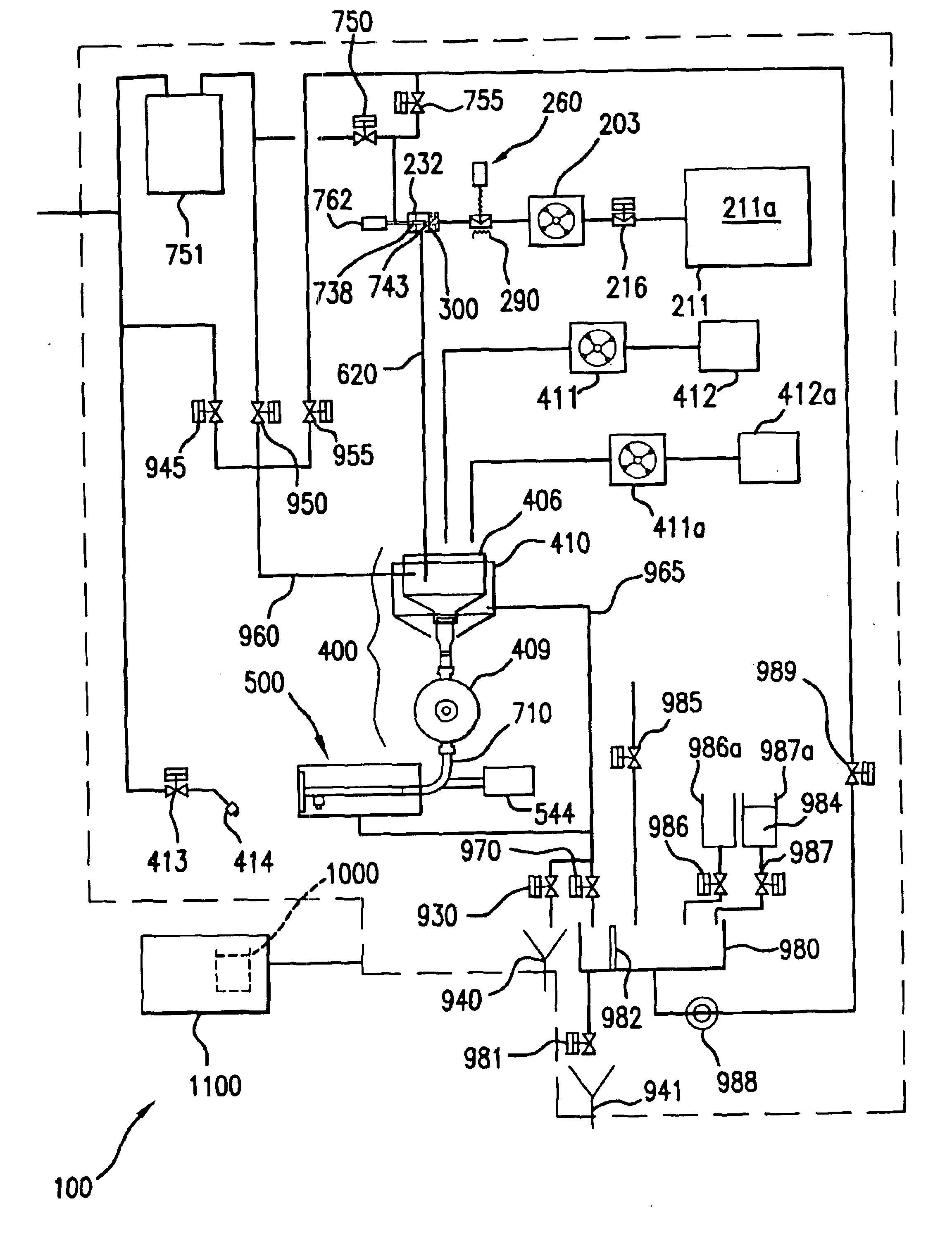
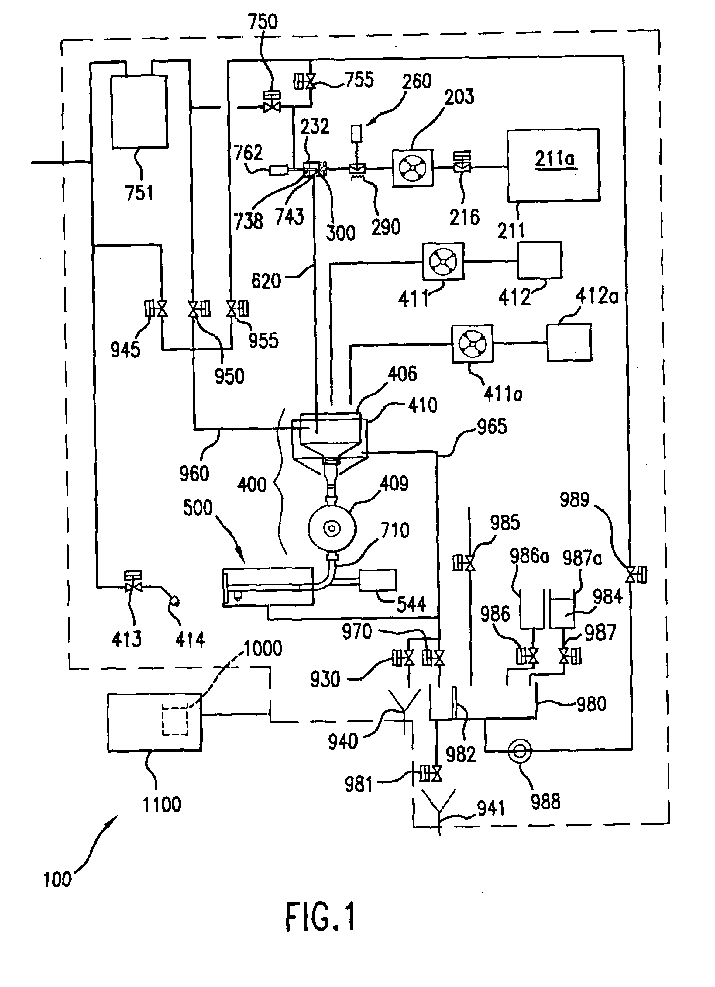
[0102]For purposes of illustration only, and with reference to FIGS. 1-3, an operating mode of the automated food dispenser in accordance with the invention will now be illustrated wherein a new reservoir 211 will be installed to replace an empty one.

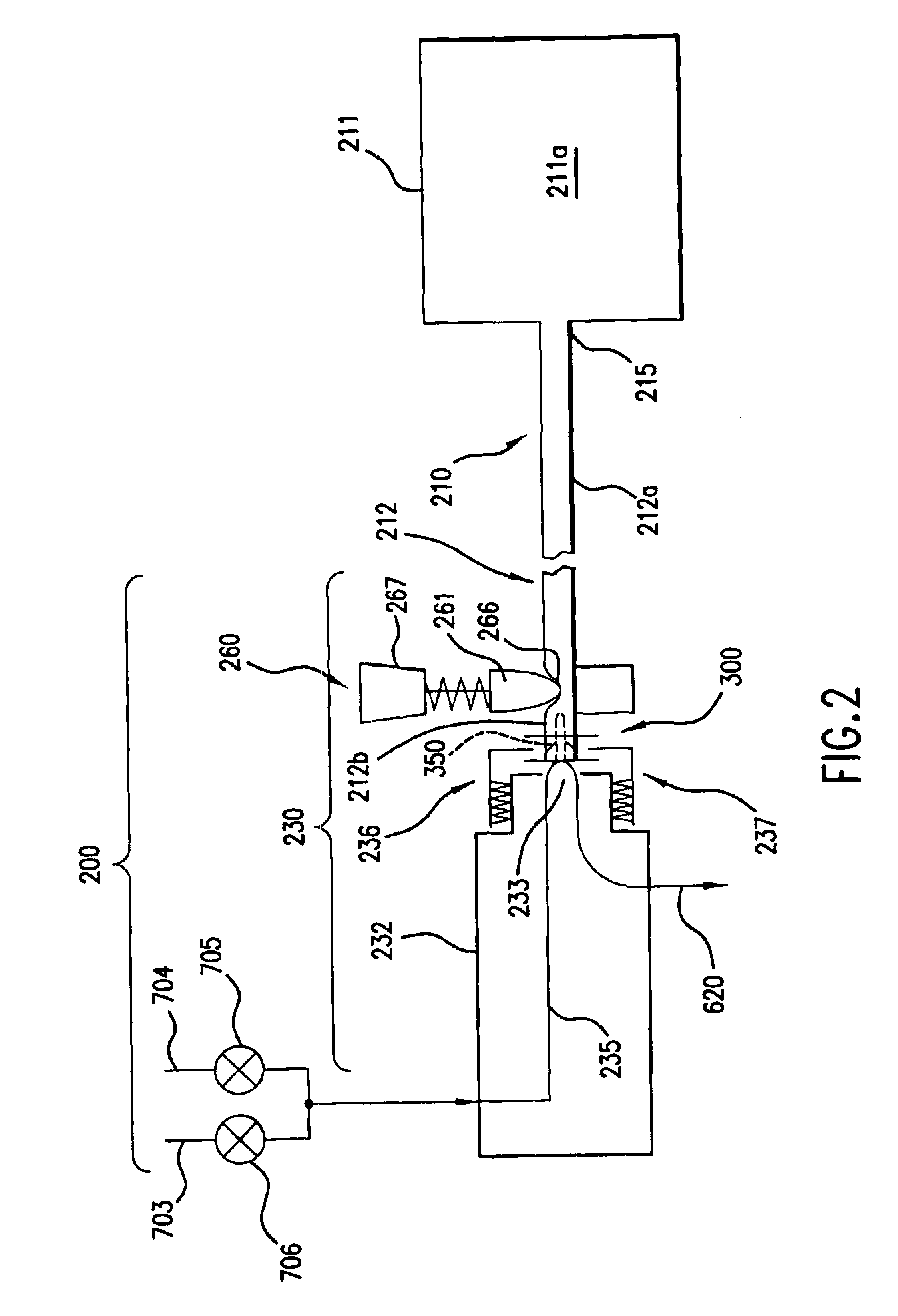
[0103]In this example, reservoir 211 is to be replaced by an operator. As embodied herein, a machine operator presses a button 1110 on control panel 1100 to indicate that the reservoir 211 will be replaced. Pinch valve 216 then is opened. In this embodiment a second pinch valve 260 is spring loaded by tension spring 263 and is opened manually by pulling the pinching member 261 away from the pinch block 262 to allow the hose 212 and reservoir 211 to be removed.

[0104]An actuator 762 on milk manifold 230 is then energized, moving projection member 738 and spear 743 backward, away from the fitment 300 area. When the spear 743 has retracted, the actuator 762 is de-energized. Electromagnetic actuator 544 of the dispens...

example ii

Product Dispensing

[0108]For purposes of illustration only, and with reference to FIGS. 1-3 and 13, an operating mode of the automated food dispenser in accordance with the invention will now be illustrated wherein food product is dispensed by the dispenser.

[0109]In this example, the dispenser is operated by an operator to dispense a milk-based cappuccino drink food product. As embodied herein, a machine operator presses a button 1120 for cappuccino on the control panel 1100 as the product selection. In response to the command, controller 1000 opens valve 216 and is turned on peristaltic pump203 to begin flow of milk based fluid 211a. The pressure generated by the pump 203 forces milk based fluid 211a past the spring loaded pinch valve 260.

[0110]Next, controller opens hot water supply valve 950 to begin a flow of hot water 820. Hot water 820 flows through water feed line 960 and milk based fluid 211a begins to flow through dispensing line 620 to the mixing bowl 406, where they begin ...


PUM


Abstract

The invention relates to an automated food product dispenser comprising an interface connection configured to establish a supply of a milk-based fluid from a reservoir (for example, a container or a bag), a mixing device configured to receive the milk-based fluid and prepare a milk based product, a nozzle in fluid association with the mixing device for dispensing the milk based product, a product flowpath configured for directing the milk based product to flow from the interface connection through the mixing device to the nozzle, and a clean-in-place flowpath assembly located in the dispenser and comprising a supply of cleaning or sanitizing fluid and a flowpath which is configured to deliver the cleaning or sanitizing fluid to or through the product flowpath. The invention also relates to a method of using and machine readable program for controlling the automated food product dispenser of the invention.

Description

BACKGROUND[0001]1. Field of the Invention[0002]The present invention relates to food product dispensing equipment and, more particularly, to the cleaning in place of areas of a food dispensing device that uses microbiologically sensitive starting material in the reconstitution and dispensing of food to the consumer. More particularly, but not exclusively, the invention relates to the automatic cleaning of beverage dispensers that use microbiologically sensitive starting components such as milk or milk liquid based concentrate.[0003]2. Background of the Invention[0004]In the foodservice area, post-mix beverage dispensers are well known which mix a concentrate or syrup with several measures of water and then dispense the mixture on demand to reconstitute a hot or cold beverage such as juice, carbonated sodas, coffee or tea. Serious sanitary problems may occur with microbiologically sensitive products such as low acid starting components that can enter into the composition of an on-dem...

Claims


Application Information

Patent Timeline
IPC IPC(8): A47J31/46A47J31/41A61L2/04A61L2/08A47J31/60A47J31/40A47J31/44B08B9/02B67D1/07B67D1/00
CPCA47J31/401A47J31/41A47J31/4485A47J31/46A47J31/60B67D1/07A61L2/08B08B9/0325B08B9/0327A61L2/04A61L2/24G07F13/06A47J31/469
Inventor CARHUFF, PETER W.MASU, TAKESHICLYDE, GENEDICKINSON, EDWARD L.HARVEY, ANDREW C.KOLVEK, EDWARD M.LAGO, MICHAEL H.
Owner NESTEC SA
Learn More