Charge-based frequency measurement bist
a frequency measurement and bist technology, applied in the direction of transmission monitoring, instruments, line-transmission details, etc., can solve the problems of affecting the time-to-market and product cost of many modem electronic systems, and the most difficult system to apply bist schemes
- Summary
- Abstract
- Description
- Claims
- Application Information
AI Technical Summary
Problems solved by technology
Method used
Image
Examples
Embodiment Construction
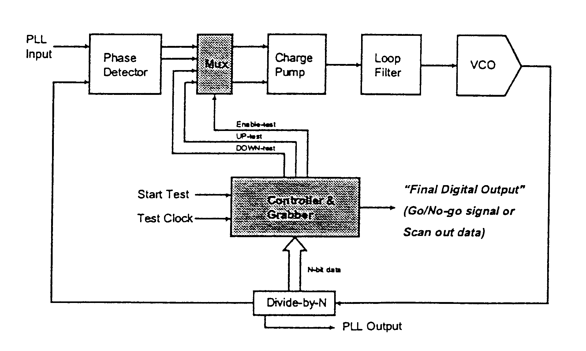
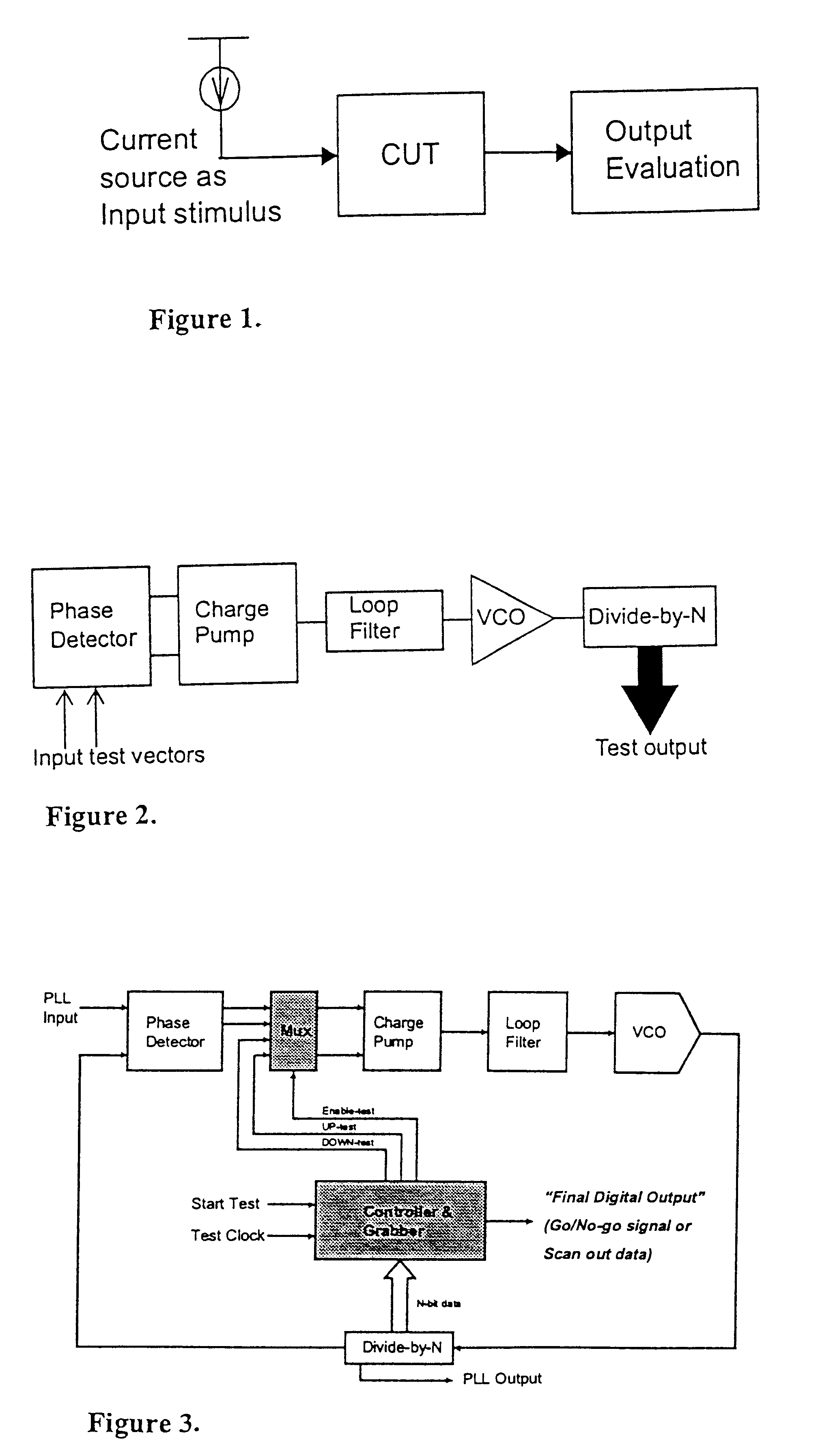
[0044]The fundamental theory of the BIST technique for a PLL is shown in FIG. 1. A constant current source is injected to the CUT (Circuit Under Test) as an input stimulus. The resulting signature output is measured and evaluated by the output evaluation block. The CUT in this case consists of analog circuitry with a relatively low input impedance. The output of the CUT is usually a voltage value which is the multiply of the input current injected and the impedance of the CUT circuit. Thus, any change in the impedance will affect the signature output of the CUT, where CUT impedance can be altered by any type of faults including physical defects.
[0045]This testing scheme can be adapted to a PLL for testing the entire PLL, by designating the loop-filter of the PLL as the CUT block. Thus, the relationship between the constant current input I to the corresponding voltage output V can be written as in equation (1) for a simple RC loop-filter, where t denotes the duration of time the inpu...
PUM
 Abstract
Description
Claims
Application Information
 - R&D
- Intellectual Property
- Life Sciences
- Materials
- Tech Scout
- Unparalleled Data Quality
- Higher Quality Content
- 60% Fewer Hallucinations
Browse by: Latest US Patents, China's latest patents, Technical Efficacy Thesaurus, Application Domain, Technology Topic, Popular Technical Reports.
© 2025 PatSnap. All rights reserved.Legal|Privacy policy|Modern Slavery Act Transparency Statement|Sitemap|About US| Contact US: help@patsnap.com


