
Light emitting semi-conductor device apparatus for display illumination

Inactive Publication Date: 2005-04-26
GE LIGHTING SOLUTIONS LLC
View PDF22 Cites 34 Cited by
  • Summary
  • Abstract
  • Description
  • Claims
  • Application Information

AI Technical Summary

Benefits of technology

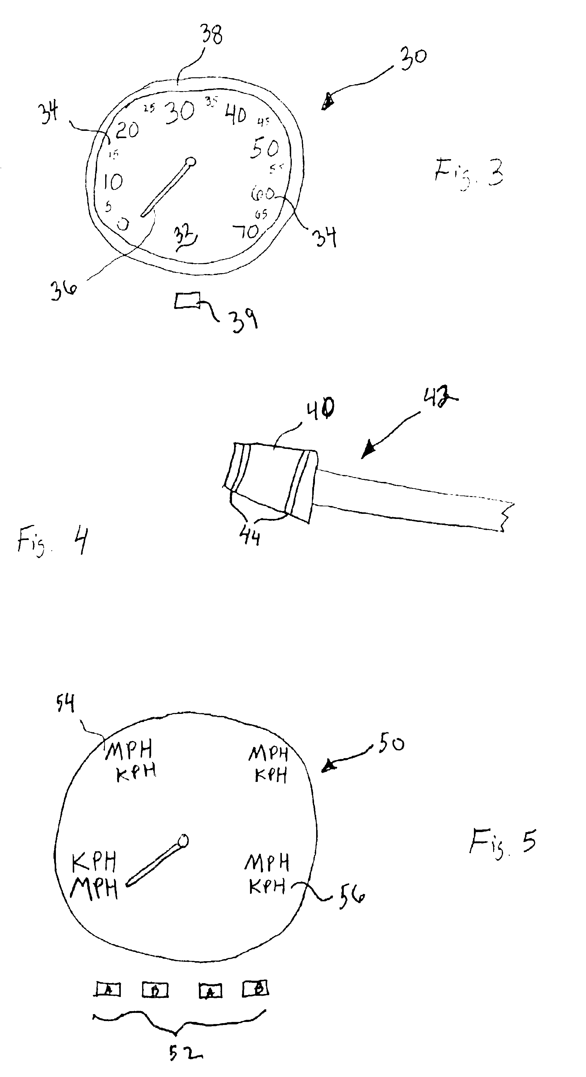
[0012]In certain exemplary embodiments of the invention, the image will be comprised of letters or numbers or will be comprised of a shaped pattern which provides general illumination of another element such as a gauge, dial, clock, etc. Accordingly, the present invention can be used to illuminate display readouts, such as a speedometer, by exposing areas of phosphor in desired areas of the display read out to light from the LED and causing the phosphor to excite in the visible region and to illuminate the display. The present invention advantageously allows the phosphor treated areas to illuminate while the remainder of the display surface remains dark.
[0013]Advantageously, the device avoids the use of multiple visible light generating LEDs, which may otherwise require separate phosphor and lensing systems.
[0015]In an alternative embodiment, the utilization of various combinations of LEDs and phosphor materials allows dimmable displays to be created. Similarly, various combinations of phosphor materials and / or LEDs can be used to create multiple color displays.

Problems solved by technology

Conventional incandescent light bulbs have limited light efficiency.
Such LED displays can operate at low power, have lite weight, and long life.
Generally, however, LED light is directional and does not evenly illuminate areas without diffusers or other light averaging structures with considerable light loss.
This is not visually desirable nor aesthetically pleasing to the eye.
Furthermore, these undesirable light patterns can light unnecessary areas and detract from the eye's ability to focus rapidly on a display.
More particularly, since it is desirable to illuminate only certain numbers, messages, dials, etc. general lighting of the are is unacceptable.
Similarly, general lighting on a surface can be problematic since the display targets (e.g. number, words, dials) may have surfaces with varied pitch which general lighting cannot readily illuminate.
This type of light distribution can be particularly troublesome when used to illuminate display surfaces, such as dashboards or control devices such as turning indicators.
Moreover, areas of high and low light intensity are undesirable.
Furthermore, the addition of phosphors to an LED device results in a relatively costly manufacturing process that yields an apparatus which may lack consistency, maintainable color temperature and lumen integrity.

Method used


Image

  • Light emitting semi-conductor device apparatus for display illumination
  • Light emitting semi-conductor device apparatus for display illumination
  • Light emitting semi-conductor device apparatus for display illumination

Examples


Embodiment Construction

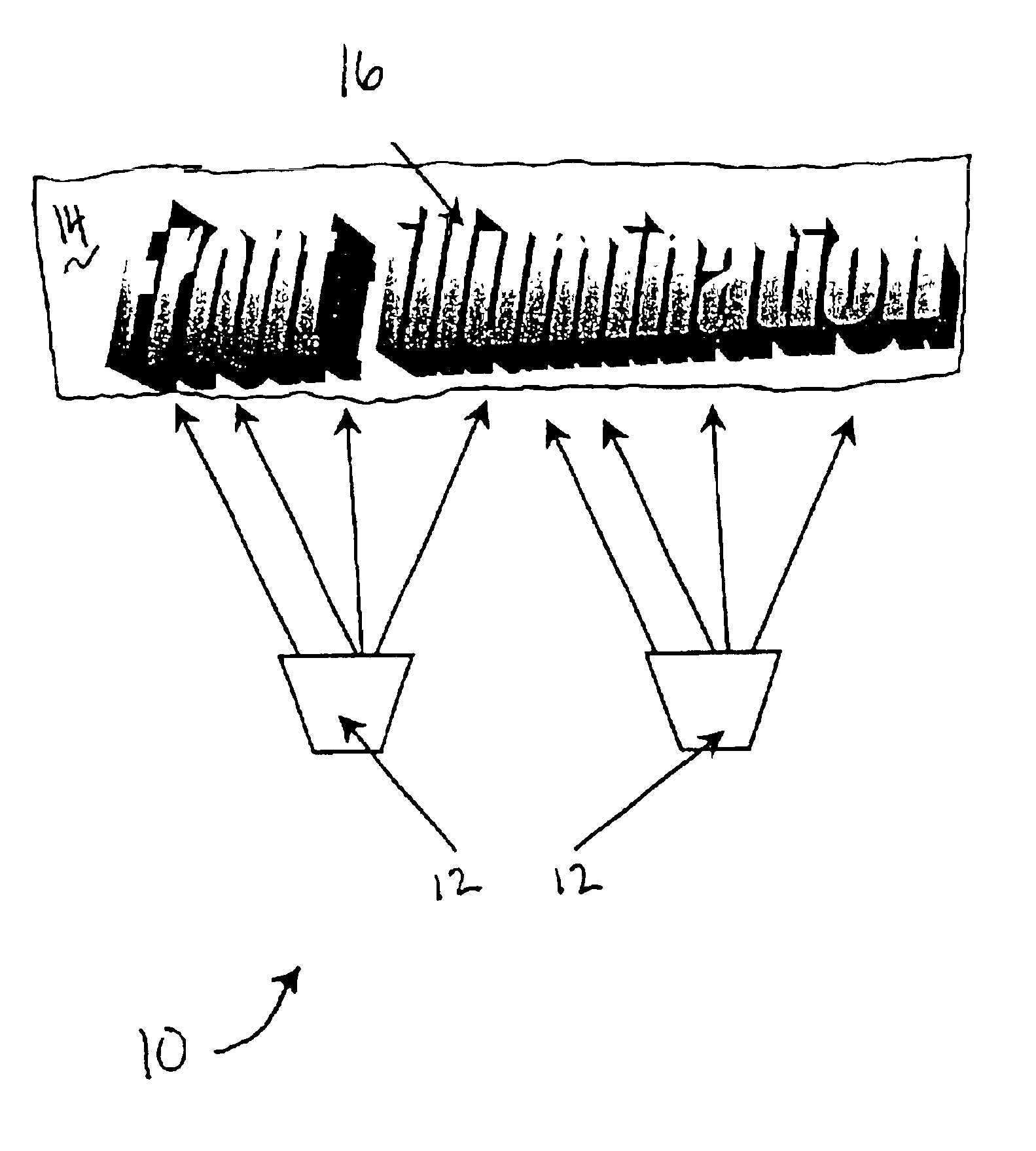
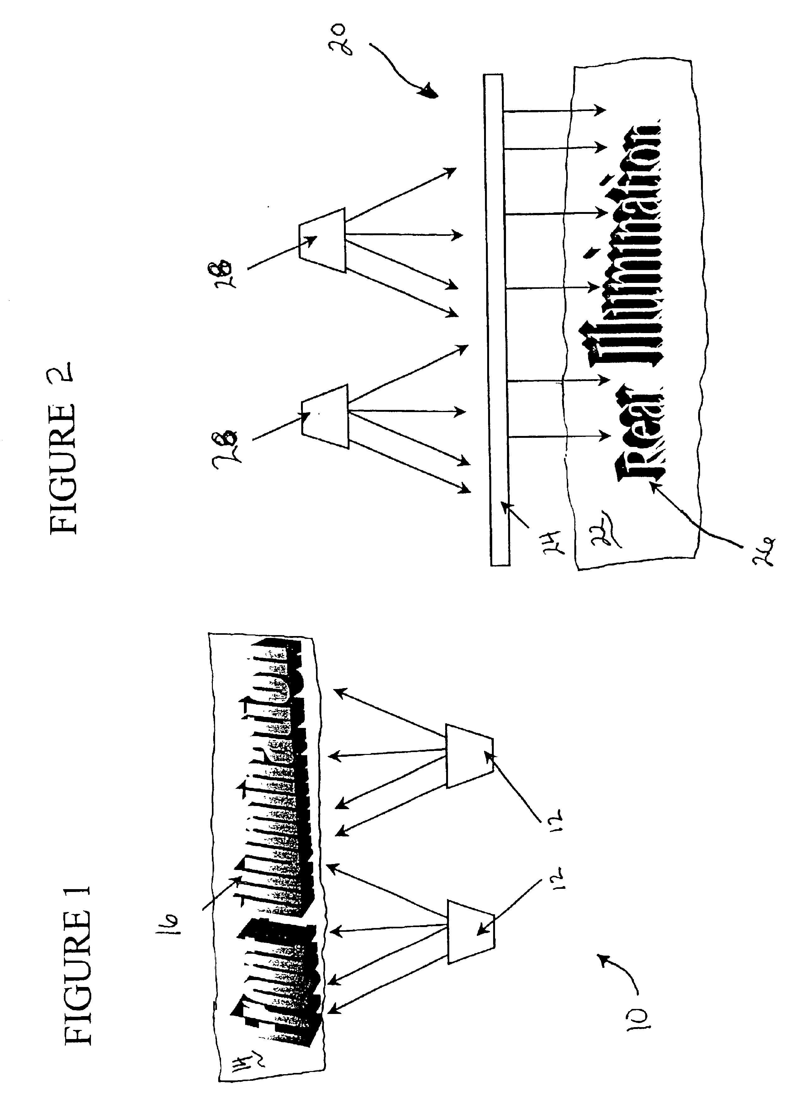
[0024]Referring now to FIG. 1, a front illumination display device 10 is depicted comprised of LEDs 12, and display surface 14 containing patterned phosphor material 16. The display surface 14 can be comprised of any material typically utilized in the construction of a display such as wood, metal, polycarbonate or other polymeric material. The phosphor can be molded therein, surface coated, or disposed in a film which is laminated on the substrate surface.

[0025]In these embodiments, ultraviolet, or blue light emitting semi-conductor devices (LED) such as those generated from silicon carbide or gallium nitride can be used. Of course, large diodes would also be highly suited to each of these embodiments. The phosphor may be patterned or the panel may have the equivalent of an etched or punched mask with desired characters etched or stamped in. The phosphor may be disposed in a film in this case which bridges the etched character openings.

[0026]Conventional LEDs can be used as well as ...


PUM


Abstract

An apparatus for visual illumination comprised of a display surface, including a phosphor material. At least one light emitting semi-conductor device is (LED) positioned to radiate the phosphor material. The LED emits electromagnetic radiation in a range which excites the phosphor material.

Description

[0001]This Application is a continuation of Ser. No. 09 / 625,127, filed Jul. 25, 2000, now abandoned.BACKGROUND OF THE INVENTION[0002]The present invention relates generally to light sources. More particularly, the present invention relates to light emitting semi-conductor light sources. The present invention has particular relevance to illumination of a display via a semiconductor device(s).[0003]Conventional incandescent light bulbs have limited light efficiency. Conventional fluorescent light bulbs include mercury. Accordingly, there is a need for a light source that has long life and high efficiency and does not create environmental concerns.[0004]One solution to this need is envisioned to be semi-conductor based light emitting diodes and laser diodes, herein after both are generally referred to as LED(s) The LED has a small size, high efficiency, can emit bright color light, and as a semiconductor element, is not vulnerable to breakage. Also, it has excellent initial driving cha...

Claims


Application Information

Patent Timeline
IPC IPC(8): B60Q1/30B60Q3/04B60Q3/00G09F13/20
CPCB60Q1/30G09F13/20B60Q3/044B60Q3/042B60Q3/12B60Q3/14
Inventor WOJNAROWSKI, ROBERT J.
Owner GE LIGHTING SOLUTIONS LLC
Learn More