
Control system and method for an internal combustion engine

Inactive Publication Date: 2005-04-26
NISSAN MOTOR CO LTD
View PDF6 Cites 39 Cited by
  • Summary
  • Abstract
  • Description
  • Claims
  • Application Information

AI Technical Summary

Benefits of technology

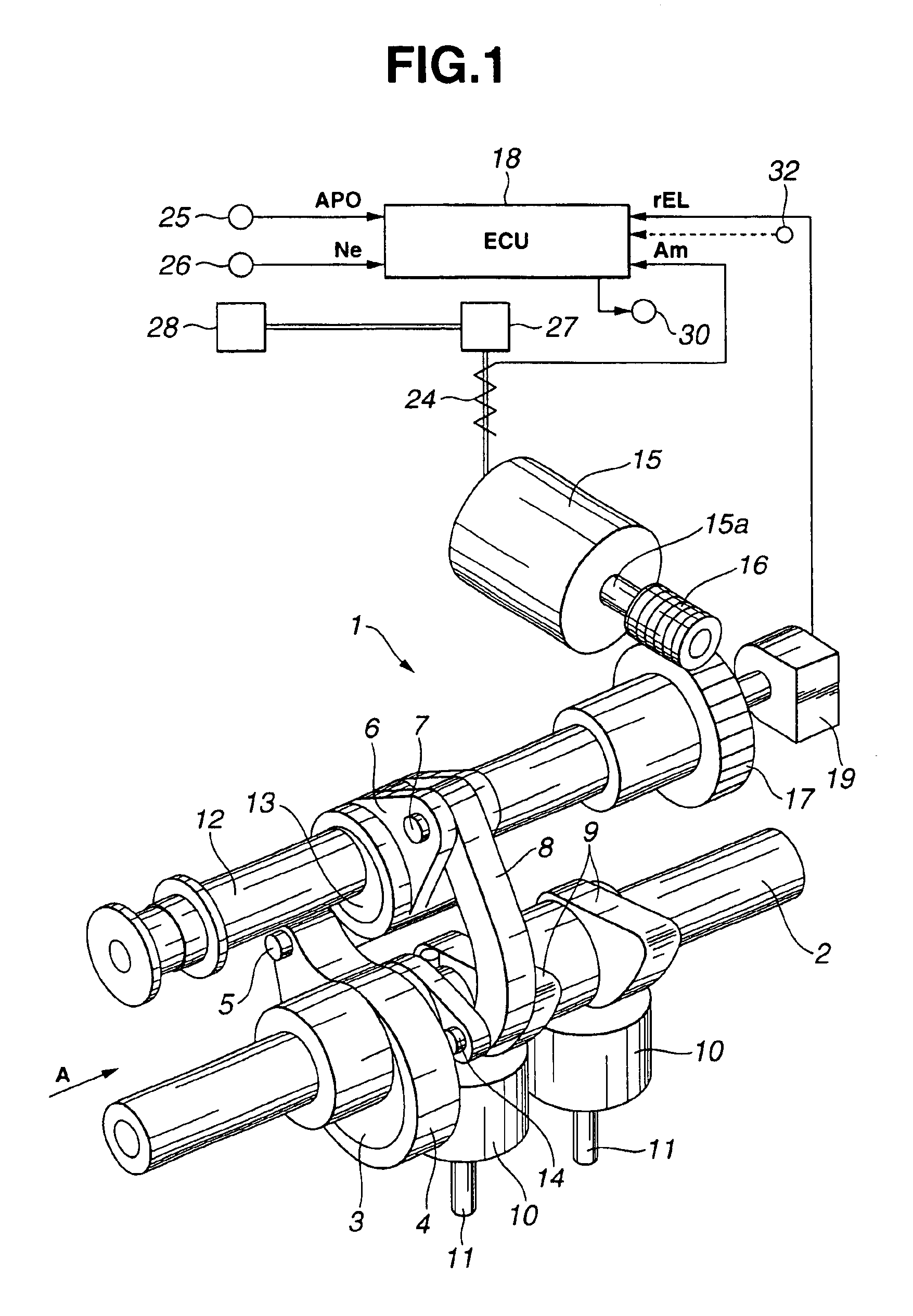
[0011]It is accordingly an object of the present invention to provide a control system for an internal combustion engine that determines a deteriorated condition of an actuator based on an operation responsiveness thereof and prevents the performance and efficiency of the engine from being deteriorated by the influence of the deteriorated operation responsiveness of the actuator.

Problems solved by technology

In the meantime, it has not heretofore been made a diagnosis of various portions of the electric motor serving as an actuator in the above-described control system, with respect to deterioration thereof that is liable to be caused after a long period of usage.
Namely, the electric motor has various portions having a possibility of being deteriorated, for example, increase in the contact resistance of a brush portion with the passage of time, partial breakage of an armature, rare short of the armature, etc. may possibly occur.
However, a detailed diagnosis with respect to such deterioration has not been made.
Accordingly, if a usual operation angle control is continued after occurrence of some deterioration of the electric motor, there is a possibility that the electric motor undergoes rapid deterioration.

Method used


Image

  • Control system and method for an internal combustion engine
  • Control system and method for an internal combustion engine
  • Control system and method for an internal combustion engine

Examples


second embodiment

[0081]FIG. 9 is a characteristic view for illustrating a method of judging a deteriorated condition of electric motor 15, that is executed by engine control unit 18, according to the present invention.

[0082]Herein, a diagnosis pattern for changing a target value of valve lift immediately after start of the engine is performed, and a deteriorated condition of electric motor 15 is determined (i.e., deterioration parameter D is calculated) based on the response time for 90% of the target value to be reached.

[0083]Immediately after start of the engine, a throttle valve (not shown) of the engine is held closed, so that the density of air downstream of the throttle valve is low and a variation of a flow rate of air in response to a variation of lift and operation angle is small. For this reason, the judgment on deterioration can be performed without giving a strange feel to a vehicle driver.

[0084]In the meantime, no influence on the drivability is caused immediately before the engine key ...


PUM


Abstract

A control system for an internal combustion engine having a variable valve operating mechanism capable of varying at least one of a valve lift and an operation angle of an engine valve continuously is provided. The control system comprises a detecting device that detects an operating condition of the variable valve operating mechanism and produces a signal representative thereof, and a controller that controls the operating condition of the variable valve operating mechanism in response to the signal from the detecting device. The controller is programmed to determine whether an operation responsiveness of the variable valve operating mechanism is lowered based on the signal from the detecting device and vary operational characteristics of the variable valve operating mechanism when the operation responsiveness of the variable valve operating mechanism is lowered. A control method is also provided.

Description

BACKGROUND OF THE INVENTION[0001]The present invention relates to a control system for an internal combustion engine having a variable control mechanism for variably controlling engine performance characteristics according to an engine operating condition. More specifically, the present invention relates to a control system and method for an internal combustion engine having a variable valve operating mechanism capable of varying at least one of a valve lift and an operating angle of an engine valve (i.e., an intake valve or an exhaust valve) in accordance with an engine operating condition.[0002]Heretofore, the assignee of this application proposed a control system for an internal combustion engine having a variable valve operating mechanism, which will be described briefly in the following.[0003]The variable valve operating mechanism is adapted for use with an intake valve and includes an eccentric cam fixedly attached to a drive shaft that is rotatable in timed relation with a cr...

Claims


Application Information

Patent Timeline
IPC IPC(8): F02D41/22F02D41/00F02D13/02F01L13/00F02D15/02F02D45/00
CPCF01L1/022F01L13/0026F02D41/0002F02D41/221F02D13/02F01L1/024F01L2013/0073F01L2800/00F01L2820/041Y02T10/42F02D2041/001F02D2041/227F02D2041/228Y02T10/18Y02T10/12Y02T10/40
Inventor NOHARA, TSUNEYASUTAKEMURA, SHINICHISUGIYAMA, TAKANOBU
Owner NISSAN MOTOR CO LTD
Learn More