Spread spectrum receiving apparatus

a spectrum receiving and spectrum technology, applied in diversity/multi-antenna systems, multiplex communication, polarisation/directional diversity, etc., can solve the problems of difficult for the base station to direct beams to the mobile station with high precision, and it is difficult to detect paths with high precision

Inactive Publication Date: 2005-04-19
MITSUBISHI ELECTRIC CORP
View PDF10 Cites 40 Cited by
  • Summary
  • Abstract
  • Description
  • Claims
  • Application Information

AI Technical Summary

Benefits of technology

[0027]The spectrum spread receiver according to one aspect of the present invention, which carries out a reverse spreading process on a signal received by a single antenna or a plurality of antennas, and also carries out a data demodulation process based upon the reverse spread signal, comprises: a path detection unit (corresponding to a path detector 140 which is described in the embodiments that will be described later) which detects a plurality of multi-path waves from the reverse spread signal, which have satisfied a predetermined standard and for outputting time-sequential positional information of the paths; a plurality of beam forming units (corresponding to complex multipliers 150 to 152 and an adder 161) which form beams by using an adaptive algorithm based upon the time-sequential positional information that is received on the basis of the path; a plurality of transfer path estimation units (corresponding to a transfer path estimating section 170 and a complex conjugate ca

Problems solved by technology

However, in the above-mentioned conventional spectrum spread receiver, in the case when the interference wave power of beams formed on the basis of a path is not regarded as the same due to the fact that the positions of mobile stations are instantaneously biased or the fact that mobile stations having different transmission signal powers exist because of different transmission speeds, the SIR is not optimized, failing to obtain a superior bit error characteristic; consequently, the resulting problem is that it is not possible to obtain an optimal channel capacity.
Moreover, in the conventional spectrum spread receiver, another problem is that, in the case when a mobile station that is a subject for communication is shifted and the shifting velocity is a high speed, it is difficult for the base station to direct beams to the mobile station with high precision.
Moreover, in the initial state for forming beams by using an adaptive array antenna in the co

Method used


Image

  • Spread spectrum receiving apparatus
  • Spread spectrum receiving apparatus
  • Spread spectrum receiving apparatus

Examples


first embodiment

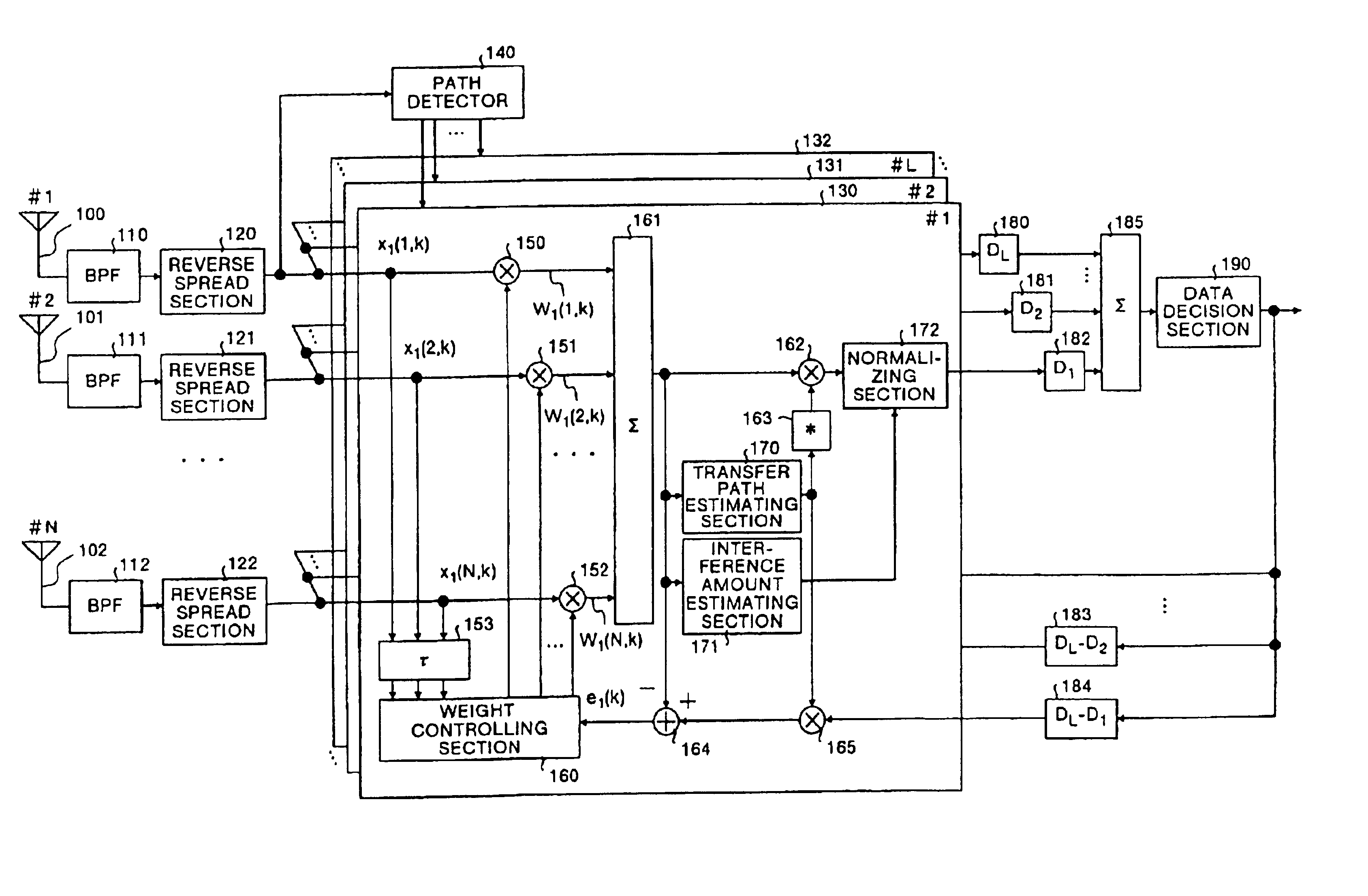
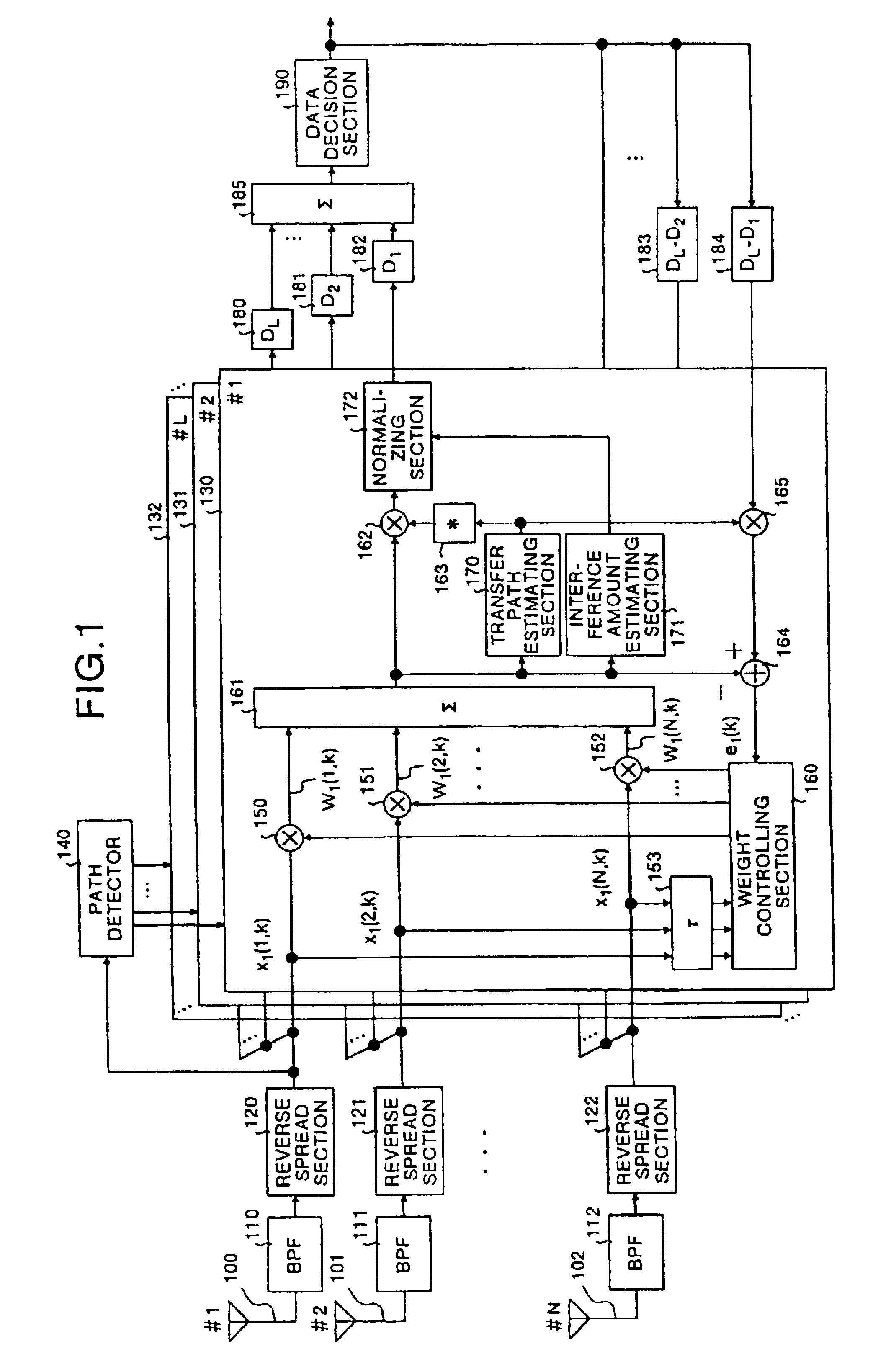
[0042]The first embodiment is related to a spectrum spread receiver in which an adaptive array antenna is used. FIG. 1 shows the construction of a spectrum spread receiver in accordance with the first embodiment. In FIG. 1, reference numerals 100, 101, . . . , 102 are antennas the number of which is represented by N (a natural number); 110, 111, . . . , 112 are band-pass filters (BPFs); 120, 121, . . . , 122 are reverse spread sections; 130, 131, . . . , 132 are beam forming sections for individually forming beams based upon L (a natural number) paths generated by signals that have been subjected to the reverse spread under an influence of a multi-path wave; 140 is a path detector; 150, 151, . . . , 152 are complex multipliers; 153 is a delay unit; 160 is a weight controlling section; 161 is an adder; 162 is a complex multiplier; 163 is a complex conjugate calculator; 164 is a substracter; 165 is a complex multiplier; 170 is a transfer path estimating section for estimating a transf...

second embodiment

[0062]In the same manner as the first embodiment, the second embodiment carries out calculations of weights based upon an adaptive algorithm such as LMS; however, it is also characterized by carrying out an integral process in which a weighting process is applied to the error signal e1(k). Here, those parts that are the same as those shown in FIG. 1 of the first embodiment are indicated by the same reference numerals, and the description thereof is omitted. Therefore, the following description will discuss the operation of the weight controlling section 160.

[0063]First, the weight controlling section 160 receives the error signal e1(k) from the subtracter, and carries out an integral process on the error signal e1(k) by using a weighting coefficient λ.

E1(k+1)=E1(k)+λ·e1(k)  (4)

[0064]λ is a weighting coefficient (01(k) is a complex number value. The complex number value E1 (k) is E1 (0)=0.

[0065]Then, the weight controlling section 160 updates / determines the weight in accordance with ...

third embodiment

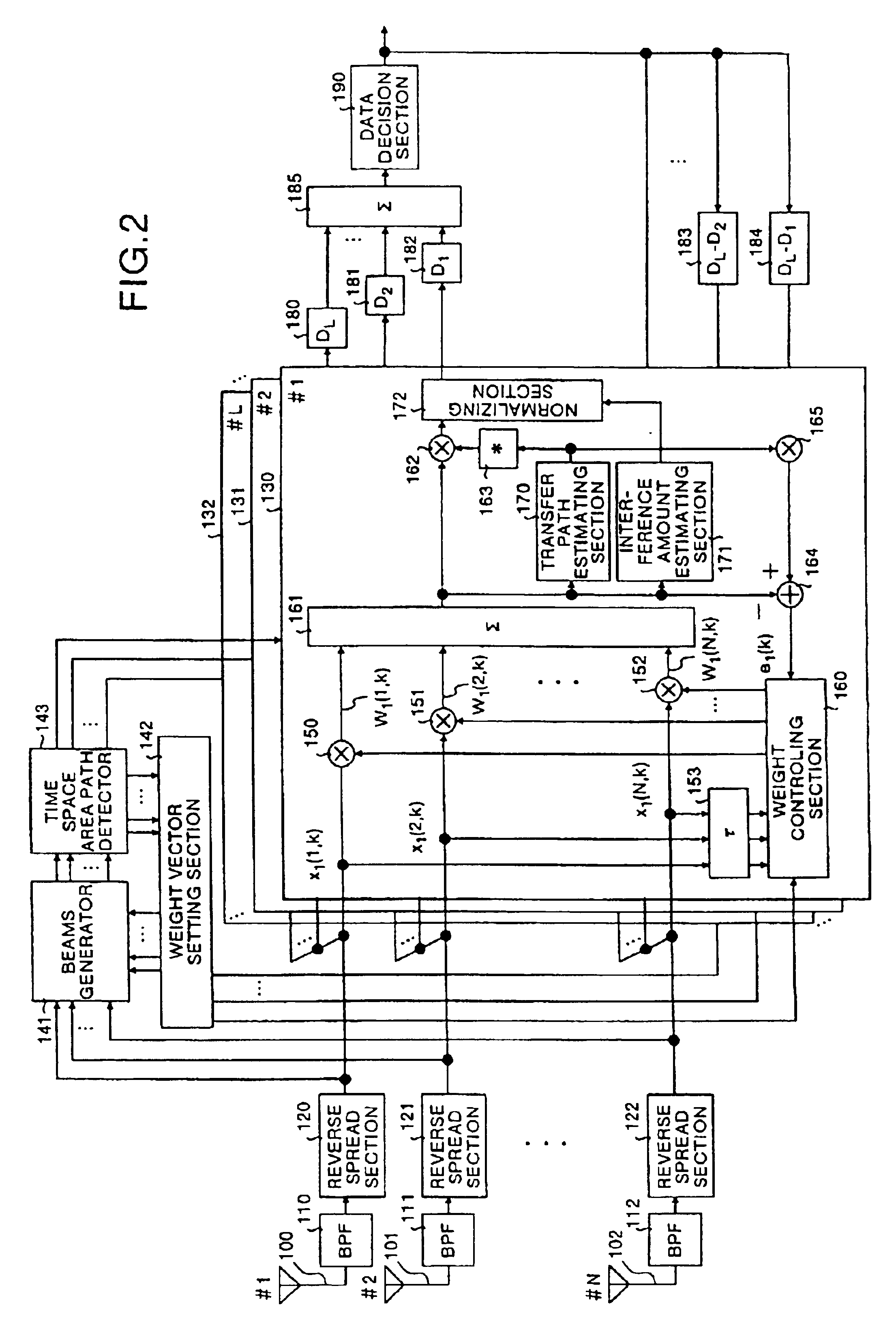
[0068]In the same manner as the first embodiment, the third embodiment will discuss a spectrum spread receiver in which adaptive array antennas are used. FIG. 2 shows the construction of the second embodiment of a spectrum spread receiver in accordance with the present invention. Here, those parts that are the same as those shown in the first or second embodiment are indicated by the same reference numerals, and the description thereof is omitted.

[0069]In FIG. 2, reference numerals 130, 131, . . . , 132 are beam forming sections for individually forming beams based upon L-number (natural number) of paths generated by signals that have been subjected to the reverse spreading process under an influence of multi-path waves, reference numeral 141 is a beams generator, 142 is a weight vector setting section, and 143 is a time space area path detector.

[0070]Next, an explanation will be given of the operation of the spectrum spread receiver having the above-mentioned arrangement. With resp...


PUM


Abstract

A path detector (140) detects a plurality of multi-path waves that have satisfied a predetermined standard from reverse spread signals, a plurality of adders (161) form beams on the basis of a path, a plurality of transfer path estimating sections (170) and complex conjugate calculators (163) calculate a transfer path estimation value, and based upon the result of the estimation, carry out a weighting process in accordance with the signal amplitude and a removing process of the phase variations. Moreover, a plurality of interference amount estimating sections (171) extract the amount of interference, a plurality of normalizing sections (172) normalize the signals that have been subjected to the phase variation removing process based upon the amount of interference, an adder (185) combines all the signals that have been normalized, and a data determining section (190) determines the signal that have been combined.

Description

TECHNICAL FIELD[0001]The present invention relates to a spectrum spread receiver that uses a Code Division Multiple Access (CDMA) System which adopts a spectrum spread modulation system. More particularly, this invention relates to a spectrum spread receiver that carries out communications by using a transfer path in which a frequency selective fading is generated.BACKGROUND ART[0002]A conventional spectrum spread receiver will be described here. Conventional spectrum spread receivers that use the CDMA system which adopts the spectrum spread modulation system have been disclosed in, for example, “Experimental Evaluation on Coherent Adaptive Array Antenna Diversity for DS-CDMA Reverse Link, The Institute of Electronics, Information and Communication Engineers, Technical Report of IEICE, RCS98-94 p.33-38, September, 1998”, and “Laboratory Experiments on Coherent Rake Receiver in Broadband DS-CDMA Mobile Radio, The Institute of Electronics, Information and Communication Engineers, Tech...

Claims


Application Information

Patent Timeline
IPC IPC(8): H04B1/707H04B7/08H04L27/14H04B1/7107H04B1/7117H04B1/712H04B7/02H04B7/10H04J13/00H04L7/00
CPCH04B7/0897H04B1/712H04B1/7113
Inventor SANO, HIROYASU
Owner MITSUBISHI ELECTRIC CORP
Why Eureka
Try Eureka