
Wear reduction of a disc surface using an adaptive dither process

a technology of wear reduction and dithering process, applied in the direction of data recording, recording head arrangement, instruments, etc., can solve the problems of corrosion of the magnetic recording layer, failure to launch the read/write head, and the reduction of the fly height, so as to achieve the effect of safe contact with the latch

Inactive Publication Date: 2005-04-19
SEAGATE TECH LLC
View PDF17 Cites 7 Cited by
  • Summary
  • Abstract
  • Description
  • Claims
  • Application Information

AI Technical Summary

Benefits of technology

[0011]The present invention (as embodied herein and as claimed below) is generally directed to an apparatus and method for reducing and dispersing wear to the surface of a rotatable disc using an adaptive dither process.
[0014]In this way, the actuator assembly can safely contact the latch during dithering without exerting sufficient force to open the latch and inadvertently move the heads out onto the user data portion of the disc. Preferably, the open latch current is measured each time the latch is opened to account for changes in system parameters over time and ensure the dither current remains at a safe level.

Problems solved by technology

As discussed below, however, a reduction in fly height may frustrate efforts to launch the read / write heads from a parked position into flight.
Breakdown of a carbon overcoat leads to corrosion of the magnetic recording layer, which can eventually render the entire rotatable disc surface inoperable as a magnetic storage medium.
An increase in stiction between the read / write head and the landing zone results in extended contact time between the read / write head and the surface of the disc.
The extended contact time accelerates wear of the carbon overcoat, which reduces the operating life of the disc drive.

Method used


Image

  • Wear reduction of a disc surface using an adaptive dither process
  • Wear reduction of a disc surface using an adaptive dither process
  • Wear reduction of a disc surface using an adaptive dither process

Examples


Embodiment Construction

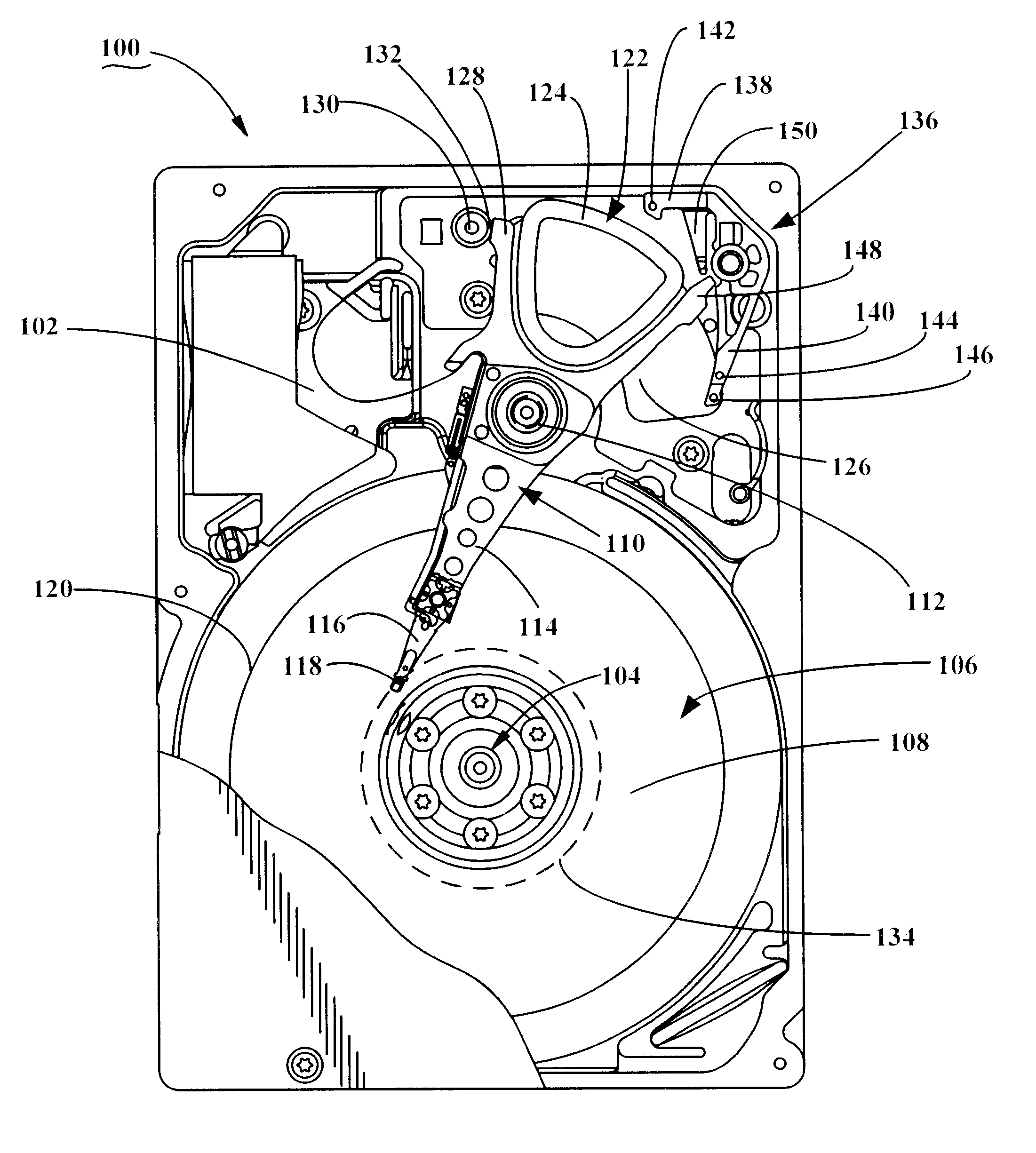
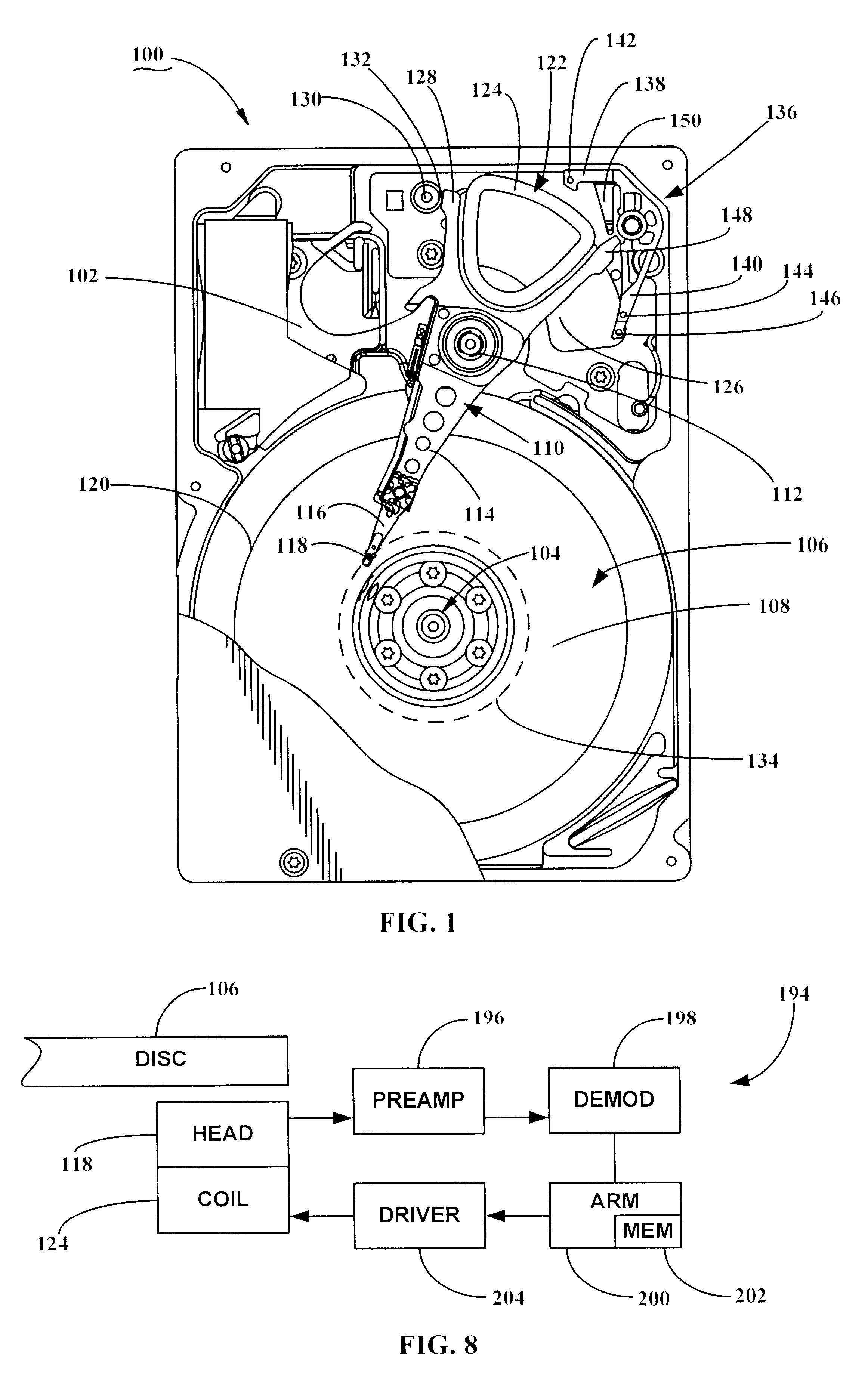
[0026]FIG. 1 shows a top view of a disc drive 100 constructed in accordance with preferred embodiments of the present invention. The disc drive 100 includes a basedeck 102 supporting various disc drive components, including a spindle motor assembly 104.

[0027]The spindle motor assembly 104 supports at least one axially aligned rotatable disc 106 having a disc surface 108. Adjacent the disc 106 is an actuator assembly 110 (also referred to as a actuator assembly (HSA)), which pivots about an actuator motor support 112 (also referred to as a bearing assembly).

[0028]The actuator assembly 110 includes at least one actuator arm 114 that supports a load arm (flexure) 116, which in turn typically supports at least one read / write head 118 (also referred as head 118) adjacent the disc surface 108. Each rotatable disc surface 108 is divided into concentric circular data tracks 120 (only one shown) over which the read / write head 118 is positionably located.

[0029]The actuator assembly 110 is con...


PUM


Abstract

Method and apparatus for reducing and dispersing wear to the surface of a rotatable disc in a disc drive using an adaptive dither process. The disc drive includes an actuator assembly that is secured in a parked position by a latch when not in use. The method includes determining an open latch current required to open the latch as the actuator assembly is moved from the parked position to a position over a user data storage portion of the disc. A dither current is subsequently applied to the actuator assembly to induce a reciprocating lateral displacement of the actuator assembly when the actuator assembly is secured in the parked position, wherein the maximum amplitude of the dither current is selected to be less than the open latch current.

Description

RELATED APPLICATIONS[0001]This application claims priority to U.S. Provisional Application No. 60 / 338,898 filed Dec. 10, 2001, entitled Voice Coil Motor Dither During Drive Spinup.FIELD OF THE INVENTION[0002]This invention relates generally to the field of data storage devices, and more particularly, but not by way of limitation, to incorporation of a method for wear reduction and dispersion of a disc surface through adaptive actuator assembly dither.BACKGROUND[0003]Disc drives are used for data storage in modern electronic products ranging from digital cameras to computer systems and networks. Typically, a disc drive includes a mechanical portion, or head disc assembly (HDA), and electronics in the form of a printed circuit board assembly (PCB), mounted to an outer surface of the HDA.[0004]The PCB controls HDA functions and provides an interface between the disc drive and its host. Generally, the HDA comprises one or more magnetic discs affixed to a spindle motor assembly for rotat...

Claims


Application Information

Patent Timeline
IPC IPC(8): G11B5/012G11B5/40
CPCG11B5/54G11B21/12G11B19/04
Inventor DUVALL, MATTHEW G.DULANEY, JAMES W.LYLE, RYAN T.SHIM, WONBO
Owner SEAGATE TECH LLC
Learn More