
Multi-spectral LADAR

a multi-spectral, ladar technology, applied in the field of remote sensing, can solve the problems of inherently limited, limited radar, and similar limitations of sonar

Inactive Publication Date: 2005-04-19
LOCKHEED MARTIN CORP
View PDF9 Cites 47 Cited by
  • Summary
  • Abstract
  • Description
  • Claims
  • Application Information

AI Technical Summary

Benefits of technology

The invention is a multi-spectral detector that can identify objects in a field of view using a passive / active system. It separates received LADAR radiation and scene radiation into different spectral components and detects them using a detector array with multiple detectors. The integrated circuit generates electrical signals based on the detected LADAR radiation and the scene radiation. The method involves detecting both the scene radiation and the LADAR radiation simultaneously. The technical effect is improved identification of objects in a field of view using a multi-spectral detector.

Problems solved by technology

A need of great importance in military and some civilian operations is the ability to quickly detect and identify objects, frequently referred to as “targets,” in a “field of view.” A common problem in military operations, for example, is to detect and identify targets, such as tanks, vehicles, guns, and similar items, which have been camouflaged or which are operating at night or in foggy weather.
While RADAR and SONAR have proven quite effective in many areas, they are inherently limited by a number of factors.
For instance, RADAR is limited because of its use of radio frequency signals and the size of the resultant antennas used to transmit and receive such signals.
Sonar suffers similar types of limitations.
However, when considered in other applications, passive systems have been found to have a number of limitations.
For instance, data provided by passive systems is sometimes difficult to interpret, since a given level of light intensity may indicate an object with low reflectivity, or the same intensity level may indicate a distant object with high reflectivity.
However, these combinations usually have many problems limiting their practicability.
For instance, SAL systems do not carry the advantages of passive infrared detection while suffering the limitations of active LADAR systems.
Combined active LADAR and passive IR systems overcome this problem, but frequently suffer from other problems.
For instance, space and weight limitations are usually severe because of the platform requirements on which the systems are deployed.
Attempts to combine active LADAR and passive IR systems have problems with these constraints because, e.g., they employ separate optical trains or separate detectors for the LADAR and IR radiation.

Method used


Image

  • Multi-spectral LADAR
  • Multi-spectral LADAR
  • Multi-spectral LADAR

Examples


Embodiment Construction

[0024]Illustrative embodiments of the invention are described below. In the interest of clarity, not all features of an actual implementation are described in this specification. It will of course be appreciated that in the development of any such actual embodiment, numerous implementation-specific decisions must be made to achieve the developers' specific goals, such as compliance with system-related and business-related constraints, which will vary from one implementation to another. Moreover, it will be appreciated that such a development effort, even if complex and time-consuming, would be a routine undertaking for those of ordinary skill in the art having the benefit of this disclosure.

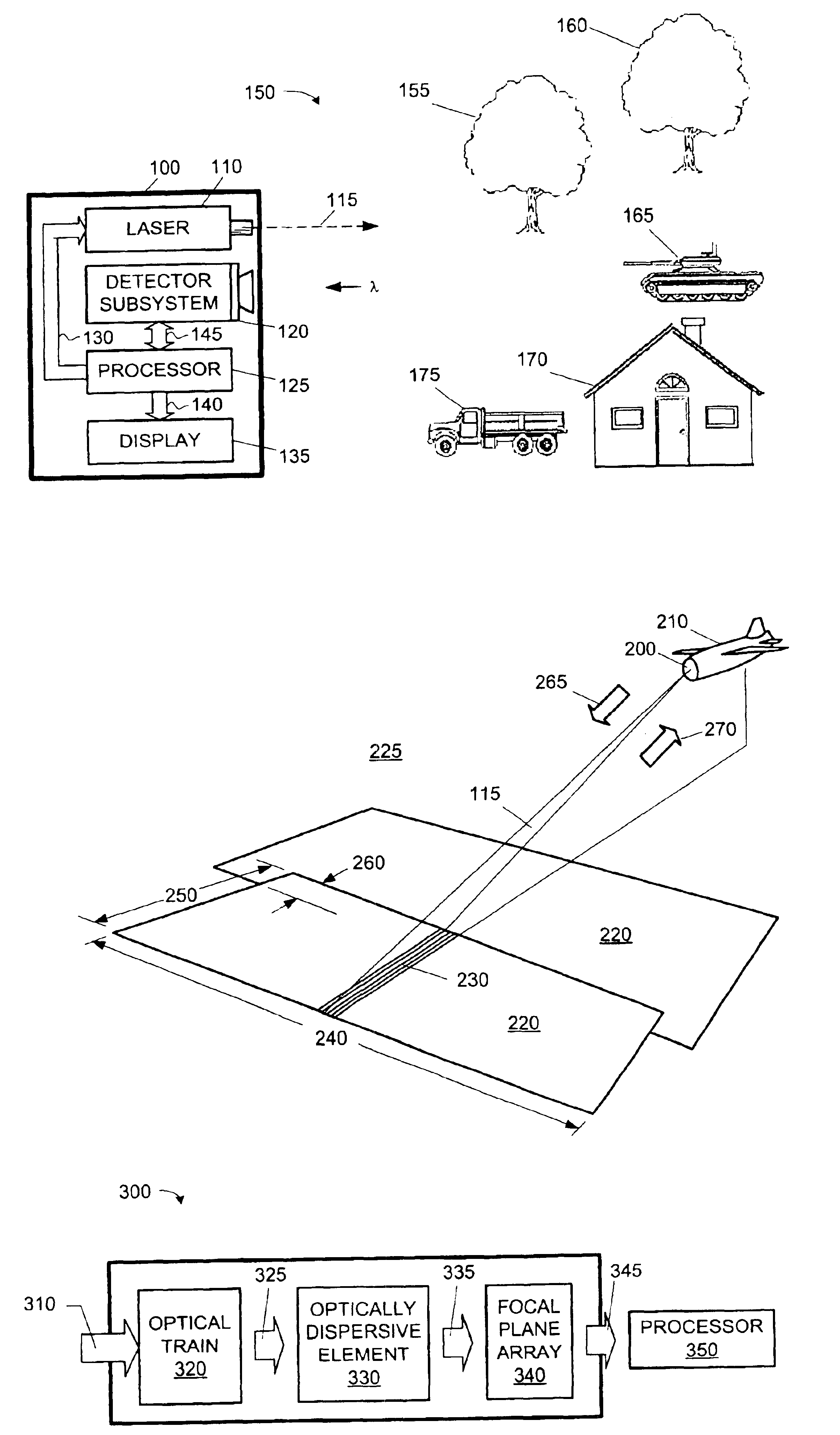
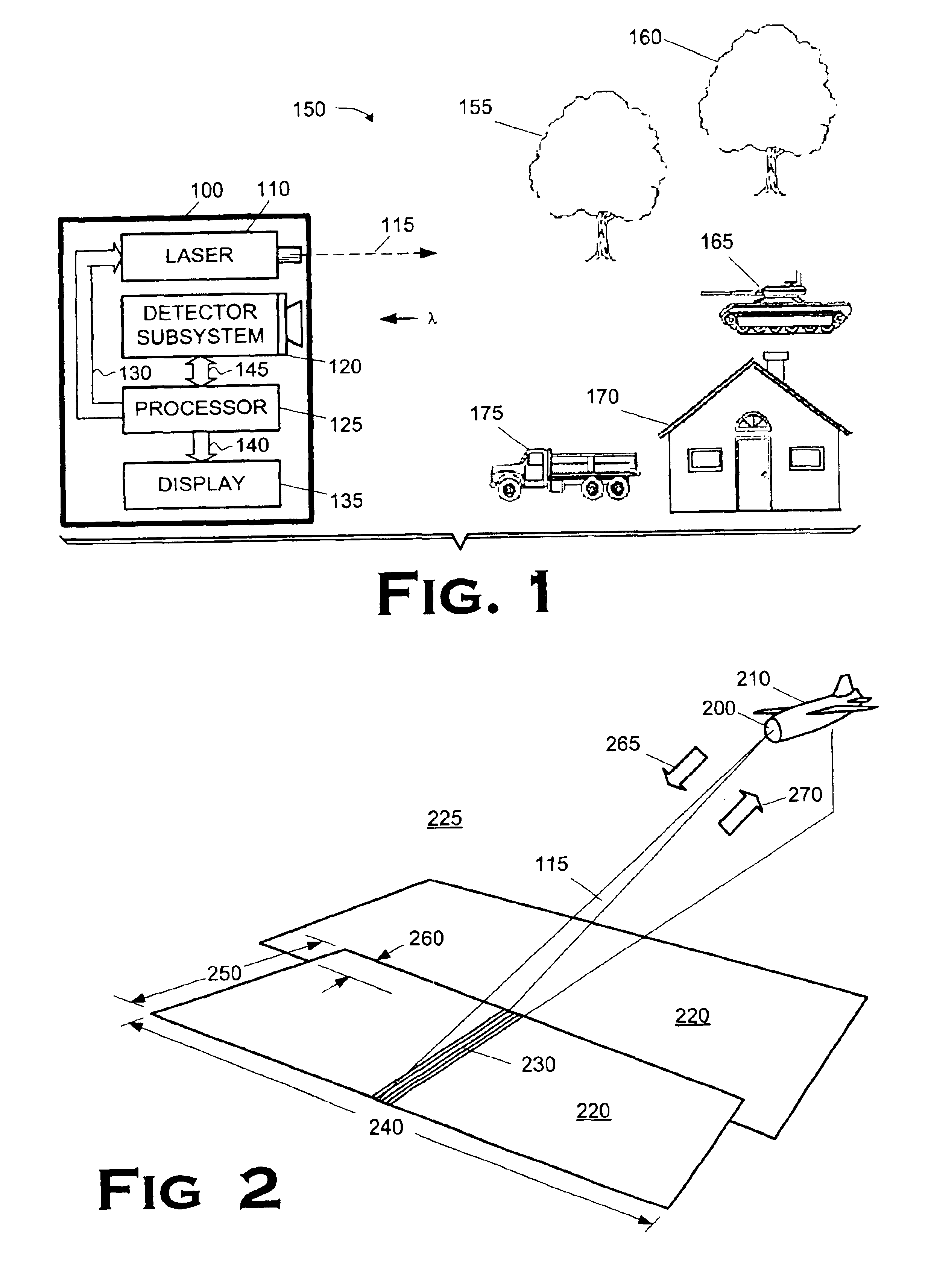
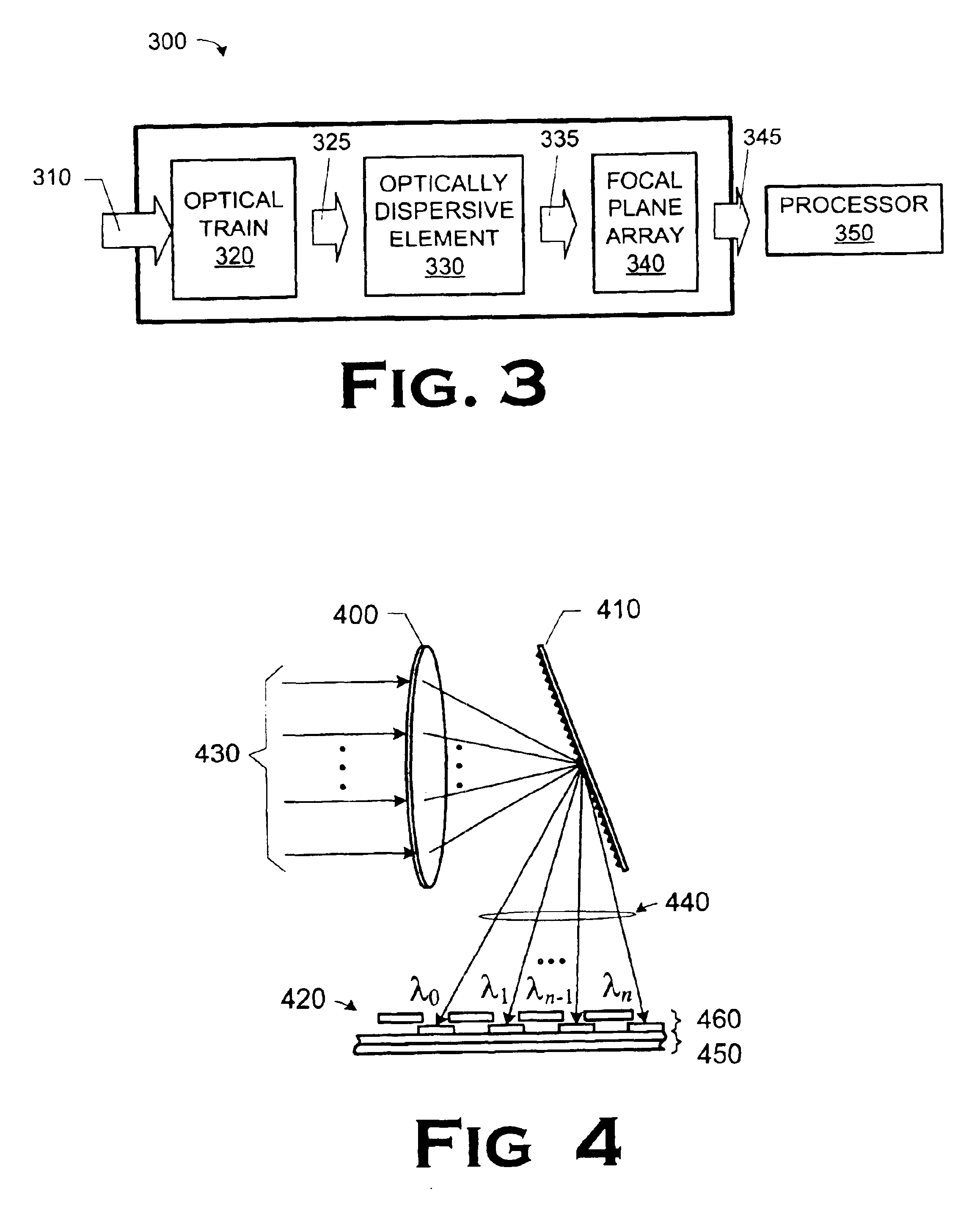
[0025]FIG. 1 illustrates an imaging system 100 constructed and operated in accordance with the present invention. The imaging system 100 includes a laser 110 that produces a laser beam 115, a detector subsystem 120, a processor 125 connected through a line 130 for operating the laser 110, and a d...


PUM


Abstract

A multi-spectral detector for use in a passive / active system and a method for use in identifying an object in a field of view are disclosed. The multi-spectral detection system comprises an optically dispersive element, a detector array, and an integrated circuit. The optically dispersive element is capable of separating received LADAR radiation and radiation received from a scene into a plurality of spectral components and distributing the separated spectral components; and a detector array. The detector array includes a plurality of detectors capable of detecting the LADAR radiation; and a plurality of detectors capable of detecting the spectral components of the scene radiation. The integrated circuit is capable of generating a plurality of electrical signals representative of predetermined characteristics of the detected LADAR radiation and the detected spectral components. The method comprises passively detecting scene radiation employing a detector array; and actively detecting LADAR radiation through the detector array in parallel with passively detecting the scene radiation.

Description

BACKGROUND OF THE INVENTION[0001]1. Field of the Invention[0002]The present invention pertains to remote sensing and, more particularly, to a combined passive / active system, e.g., a passive infrared / active LADAR system.[0003]2. Description of the Related Art[0004]A need of great importance in military and some civilian operations is the ability to quickly detect and identify objects, frequently referred to as “targets,” in a “field of view.” A common problem in military operations, for example, is to detect and identify targets, such as tanks, vehicles, guns, and similar items, which have been camouflaged or which are operating at night or in foggy weather. It is important in many instances to be able to distinguish reliably between enemy and friendly forces. As the pace of battlefield operations increases, so does the need for quick and accurate identification of potential targets as friend or foe, and as a target or not.[0005]Techniques for identifying targets have existed for man...

Claims


Application Information

Patent Timeline
Patent Type & Authority Patents(United States)
IPC IPC(8): G01S17/89G01S17/00G01S17/87G01S7/481G01C1/00G01C3/08G01S7/4863G01S17/894
CPCG01S7/481G01S17/89G01S7/4802G01S7/4816G01S7/4863G01J3/0291G01J3/0264G01J3/0289G01J3/10G01J3/18G01J3/26G01J3/36G01J3/0208G01J3/027G01J3/2823G01S17/87G01J2003/2826G01S17/894
Inventor EVANS, BRUNO J.MITRA, PRADIP
Owner LOCKHEED MARTIN CORP
Learn More