
Sutureless implantable device and method for treatment of glaucoma

a sutureless, implantable technology, applied in the field of medical devices and methods, can solve the problems of vascular congestion, obstruction or blockage of aqueous humor drainage from the anterior chamber, and defect in the functional drainage system, and achieve the effect of minimal discomfort and easy fitting for patients

Inactive Publication Date: 2005-04-19
REVISION OPTICS
View PDF4 Cites 110 Cited by
  • Summary
  • Abstract
  • Description
  • Claims
  • Application Information

AI Technical Summary

Benefits of technology

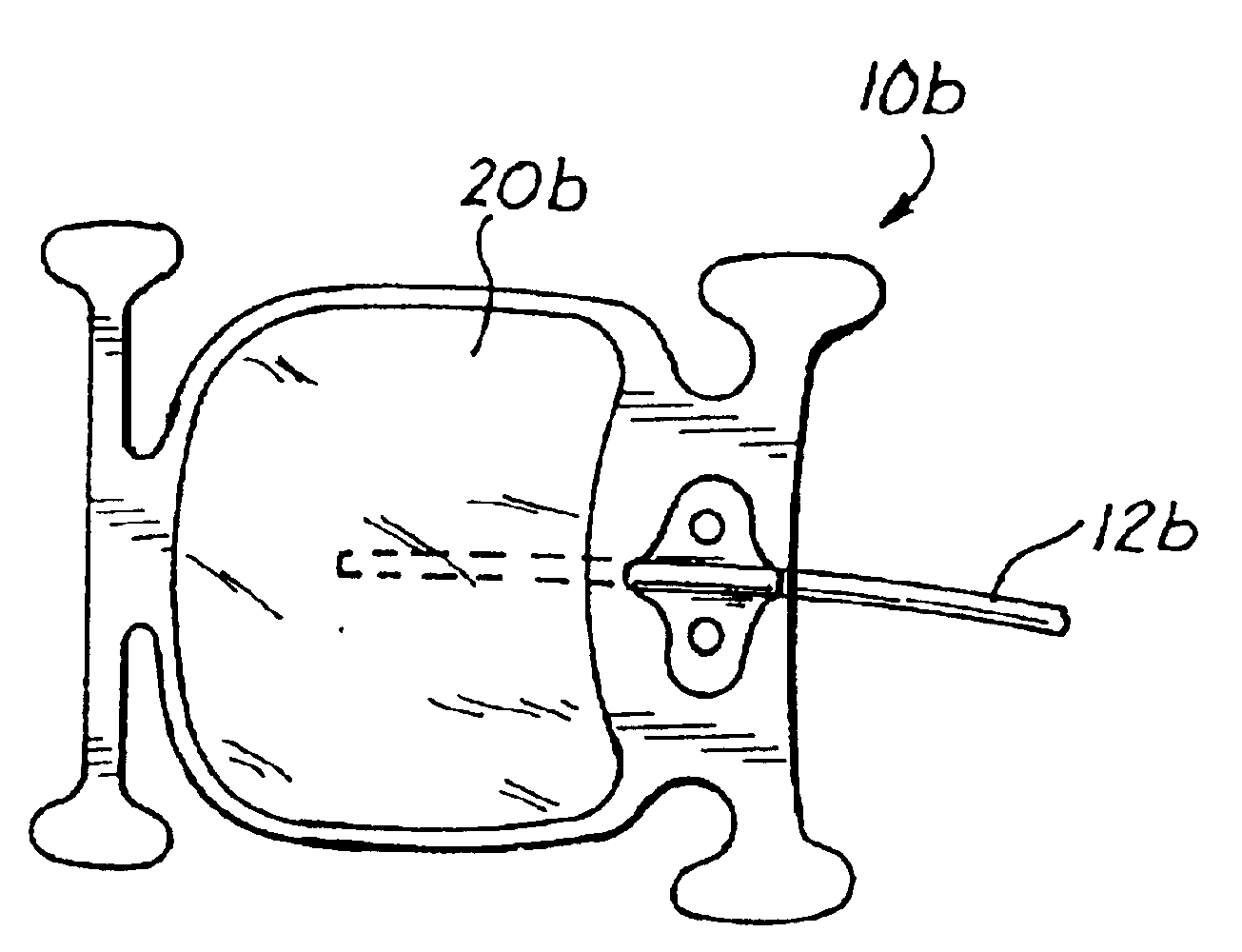
[0019]Further in accordance with the invention, there are provided fluid shunting devices which are implantable in the eye of a mammalian patient, within a subconjunctival pocket formed between two rectus muscles which are anatomically attached to the eye at spaced-apart locations, to control the pressure of fluid within the anterior chamber of the eye without the use of sutures to hold the device in its desired implanted position. A sutureless implantable device in accordance with this aspect of the invention may comprise a) a tube which has a proximal end, a distal end, a side wall, and a lumen extending longitudinally therethrough, b) a diffusion chamber which has an inner cavity formed therewithin. The diffusion chamber of the device is mounted on the proximal end of the tube, such that fluid which enters the distal end of the tube may flow through the lumen of the tube and into the inner cavity of the diffusion chamber. The distal end of the tube is insertable into the anterior chamber of the eye while the diffusion chamber remains positioned within a subconjunctival pocket, posterior to the limbus. The diffusion chamber has a posterior portion which is wider than the distance between the locations at which the adjacent rectus muscled are attached to the eye, and an inter-muscular portion which is slightly narrower than the distance between the rectus muscle attachment points. Preferably, the diffusion chamber also has an anterior portion which like its posterior portion, is wider than the distance between the adjacent rectus muscle attachment points. Such preferred sizing and configuration of the diffusion chamber allows it to be implanted within the subconvunctival pocket with its inter-muscular portion between the rectus muscle attachment points, its anterior portion extending anterior to the rectus muscle attachment points, and its posterior portion extending posterior to the rectus muscle attachment points. When so implanted, the diffusion chamber will remain in substantially fixed position and will be prevented by its engagement with the adjacent rectus muscles from undergoing substantial migration or movement in the longitudinal or lateral directions, without the need for sutures to anchor the diffusion chamber in place. Also, the diffusion chamber may be formed in a generally concave configuration which is analogous to the contour of the ocular bulb, thereby allowing the device to fit easily upon the scleral floor of the subconjunctival pocket, with minimal outward protrusion or tenting of the conjunctival tissue, and minimal discomfort to the patient.

Problems solved by technology

In general, glaucoma results from a defect in the functional drainage system, whereby naturally occurring endogenous fluid (e.g., aqueous humor) is drained from the interior of the eye.
“chronic simple glaucoma”“simple glaucoma”, “wide-angle glaucoma) the angle of the anterior chamber remains normal, but the drainage of aqueous humor from the anterior chamber is impeded or blocked by other means, such as edema or swelling of the trabecular spaces, abnormal pigment dispersion, or non-perforating injury to the eye resulting in vascular congestion.
However, these various drug therapies for glaucoma are sometimes associated with significant untoward effects, including headache, blurred vision, allergic reactions, retinal detachment, phacodinesis, histological changes within the eye and potential interactions with other drugs.
The major problems associated with these surgical filtration procedures stem from the size of the opening or hole made into the anterior chamber.
Moreover, such glaucoma filtration surgery is often unsuccessful due to the formation of dense fibrovascular connective tissue (e.g., scar tissue) around the surgical opening formed into the anterior chamber.
Such proliferation of connective tissue tends to close off the surgically-formed opening into the anterior chamber, thereby deterring or preventing the desired filtration of aqueous humor into the subconjunctival space.
The major disadvantage associated with the use of implantable shunts for treatment of glaucoma is that, in the immediate post operative period, the shunt may facilitate excessive fluid drainage which results in hypotony within the anterior chamber, flattening of the anterior chamber and potential choroidal detachment and / or phthisis bulbi.
Such excessive post-operative fluid outflow may also result in expansion of the fibrous capsule located beneath the rectus muscles of the eye.
Such expansion of the fibrous capsule can stretch and tighten the rectus muscles, thereby inducing heterotropia and impairing the motility of the eye in the quadrant wherein the implant is located.
Additionally, due to the size of some of these shunt devices, the bulky presence of the device itself within the subconjunctival space can cause scleral erosion, changes in the natural curvature of the eye, or damage to adjacent vasculature and tissue.
Other problems associated with the use of implantable shunt devices for the treatment of glaucoma involve friction and wear imparted by the implanted shunt device, irritation of the iris endothelium caused by insertion of the shunt device into the anterior chamber, and migration of microbes, cells, proteins or other matter through the lumen of the shunt device and into the anterior chamber of the eye.
Also, the surgical procedures used to implant the prior art fluid shunting devices have typically been laborious in nature and have typically required that suturing of the fluid shunting device to the surrounding tissue of the host, to hold the fluid shunting device at its desired location within the eye.
The installation of sutures to anchor the implanted fluid shunting device is time consuming and, in cases where such sutures are not properly placed, can result in undesirable tugging, traction or stress on the surrounding tissue and / or disconfiguration of the implanted device.
Also, the installation of such sutures can result in unintentional, iatrogenic perforation of the anterior or posterior chabber of the eye, with resultant leakage of aqueous or vitreous humor and / or resultant cellular ingrowth and opacification of the aqueous and / or vitreous humor.
In hydrocephalus, excessive amounts of cerebrospinal fluids accumulate within skull, generally resulting in elevated intracranial pressure.
The chronic elevation in intracranial pressure caused by such excessive cerebrospinal fluid within the skull typically results in enlargement of the head, prominence of the forehead, brain atrophy, mental deterioration, and convulsions.
One complication associated with the use of implantable shunt devices to drain fluid from body cavities is that proteins, cellular matter, or other debris may block the lumen of the shunt tube thereby interfering with the drainage of fluid through the tube.
Also, proliferation of tissue or blebs may compress, collapse, or block the shunt tube.
Moreover, pathogenic microorganism or irritating proteins or other matter may migrate through the lumen of the shunt tube into the affected body cavity in a manner which can lead to iatrogenic infection, irritation or inflammation of the affected body cavity.
Given the above-summarized limitations and drawbacks associated with the implantable fluid-shunting devices of the prior art, it is apparent that no single fluid-shunting device has proven to be optimal for all applications.

Method used


Image

  • Sutureless implantable device and method for treatment of glaucoma
  • Sutureless implantable device and method for treatment of glaucoma
  • Sutureless implantable device and method for treatment of glaucoma

Examples


Embodiment Construction

[0034]The following detailed description, and the accompanying drawings to which it refers are provided for purposes of exemplifying and illustrating representative examples and embodiments of the invention only, and are not intended to limit the scope of the invention in any way. Indeed, no effort has been made to exhaustively illustrate and describe ail possible embodiments and configurations in which the present invention may take physical form.

i. Construction and Configuration of the Fluid Shunting Device

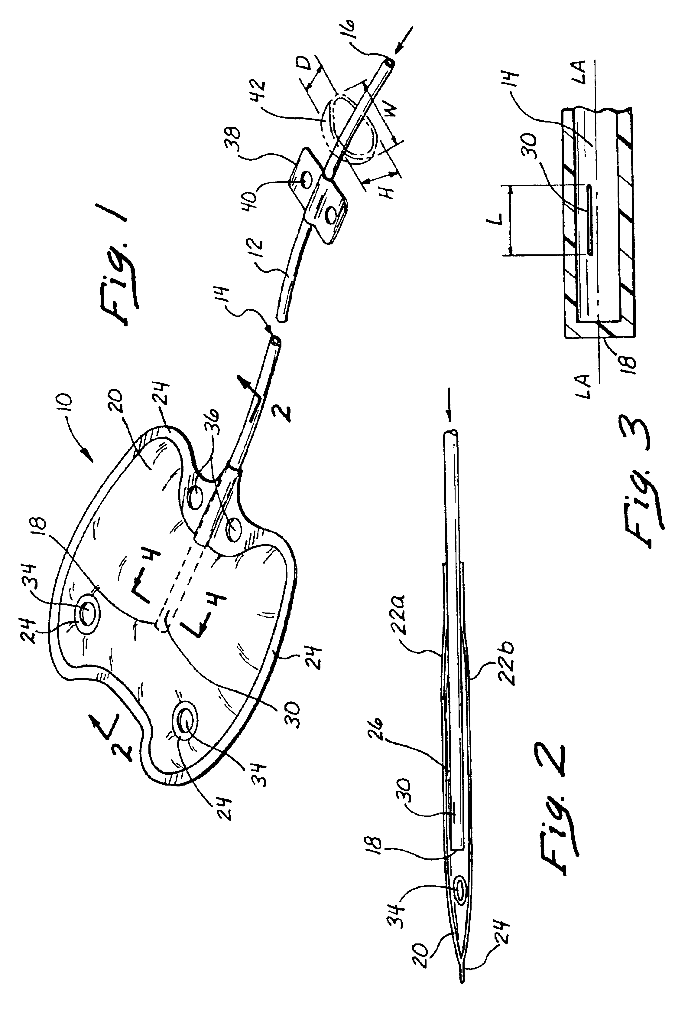
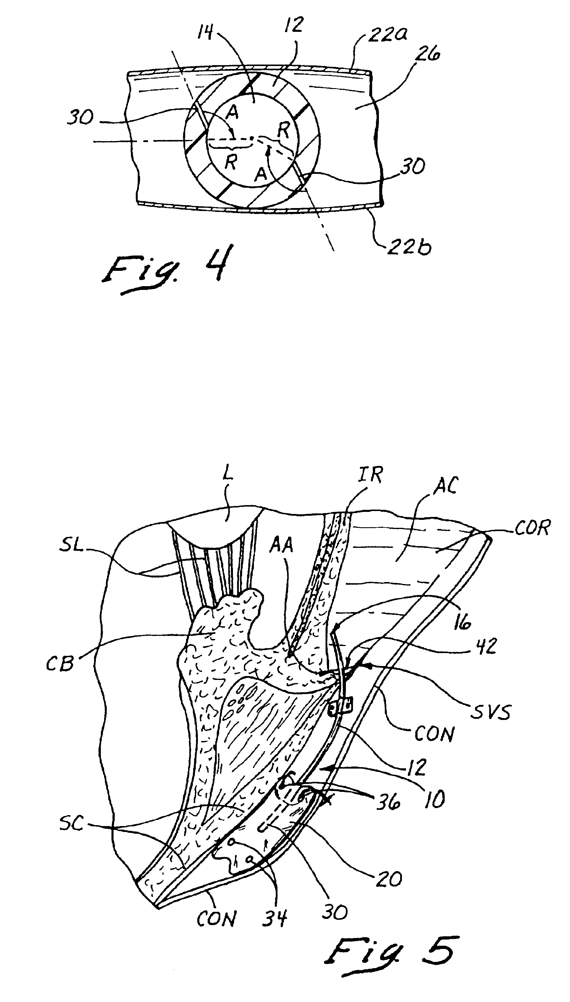
[0035]With reference to FIGS. 1-4, there is shown a first embodiment of an implantable fluid shunting device 10 comprising an elongate tube 12 having a lumen 14 extending longitudinally therethrough and a diffusion chamber 20 mounted on the proximal end thereof. The tube 12 has an open distal end 16, a closed proximal end 18 and a pressure openable aperture 30 which is located in a proximal portion PP of the tube 12 which extends into the interior of the diffusion chamber 20.

[00...


PUM


Abstract

Sutureless, implantable fluid shunting devices and associated methods for controlling the pressure of fluids within anatomical spaces or cavities of the body. The device generally comprises a tube having a diffusion barrier (e.g., diffusion chamber) formed on a proximal end thereof. Fluid which flows through the tube will collect within the diffusion chamber and will diffuse outwardly therethrough. However, the presence of the diffusion chamber will prevent microbes, cells or other matter from interfering with or backflowing through the tube. Additionally, the tube may be provided with a pressure-openable aperture through which fluid from the tube may flow into the diffusion chamber. Such pressure-openable aperture will remain closed, until the pressure of fluid within the tube exceeds a predetermined maximum pressure PMAX. In this manner, the pressure-openable aperture will limit the amount of fluid drained from the anatomical space or cavity of the body, thereby avoiding hypotony within such anatomical space or cavity. The diffusion barrier of the device is preferably configured to fit between, and to be engaged by, adjacent recti muscles of the eye. Such engagement of the diffusion barrier with the adjacent recti muscles serves to prevent unwanted migration or post-implantation movement of the device, without the need for suturing of the device to the tissue of the eye.

Description

RELATED APPLICATION[0001]This application is a continuation-in-part of U.S. patent application Ser. No. 08 / 738,332 filed Oct. 25, 1996 now U.S. Pat. No. 6,007,510 entitled “Implantable Devices and Methods for Controlling the Flow of Fluids Within the Body.”FIELD OF THE INVENTION[0002]The present invention relates generally to medical apparatus and methods, and more particularly to a device which is implantable in a mammalian body to control the pressure of fluid within a body cavity by shunting such fluid to another site within the body, when the fluid pressure within the body cavity reaches a pre-determined level.BACKGROUND OF THE INVENTION[0003]A number of diseases and disorders in humans and other mammals are characterized by the build-up of excessive fluid pressure within one or more body cavities. In many instances, implantable devices or surgical procedures may be used to shunt excessive fluid from the body cavity wherein the excessive pressure build up is present, to one or m...

Claims


Application Information

Patent Timeline
IPC IPC(8): A61M27/00A61F9/007A61M1/00
CPCA61F9/00781A61M27/006A61M27/002A61F2250/0003
Inventor NIGAM, ALOK
Owner REVISION OPTICS
Learn More