Carburetor

Active Publication Date: 2005-04-19
ZAMA JAPAN
View PDF25 Cites 22 Cited by
  • Summary
  • Abstract
  • Description
  • Claims
  • Application Information

AI Technical Summary

Benefits of technology

[0007]The present invention was developed to solve the above-described problems and is principally aimed at providing a carburetor capable of supplying predetermined fuel in any operating range of an engine, but particularly in a low range of rotation, allowing stable operation.
[0009]Fuel (negative pressure fuel) whose flow rate corresponds to the air intake quantity in the entire range of operation from engine start-up to full load is delivered to the air intake passage by the first fuel system. The flow rate of this negative pressure fuel is the basic flow rate set by the maximum flow regulating means and the mechanical fuel control means. Start-up and warm-up is performed with a rich mixture by a procedure in which the second fuel system delivers fuel (positive pressure fuel) to the air intake passage when the engine is started. Because the flow rate of the positive pressure fuel is adjusted by the electrical control means, the objective of allowing stable start-up, warm-up, and subsequent idling can be achieved.
[0011]Adopting these approaches allows fuel to be supplied in an appropriate amount through start-up and warm-up, allows further ease of start-up, and provides further stability during warm-up. By performing fuel flow rate control with two fuel systems in a specific range of degrees of opening of the throttle valve, the engine can be stably operated at a required target rotational speed of the engine.

Problems solved by technology

When an engine to which fuel is supplied by the carburetor described above is operated, those components in the fuel passage extending from the constant fuel chamber and through the air intake passage of the carburetor that easily move due to engine vibrations may create inconsistencies in the fuel flow quantity.
The weight of fuel in the fuel passage and in the constant fuel chamber may change due to the orientation of equipment mounted in the engine, creating inconsistencies in the fuel flow quantity.
Inconsistencies in the fuel flow greatly affect the engine operating characteristics at start-up, warm-up, and other areas of operation.
However, drawbacks remain in the above-described conventional start-up fuel supply means because the feed rate may at times be inconsistent and at other times uniform, it is impossible to ensure stable warm-up even if start-up can be performed.

Method used


Image

  • Carburetor
  • Carburetor
  • Carburetor

Examples


Embodiment Construction

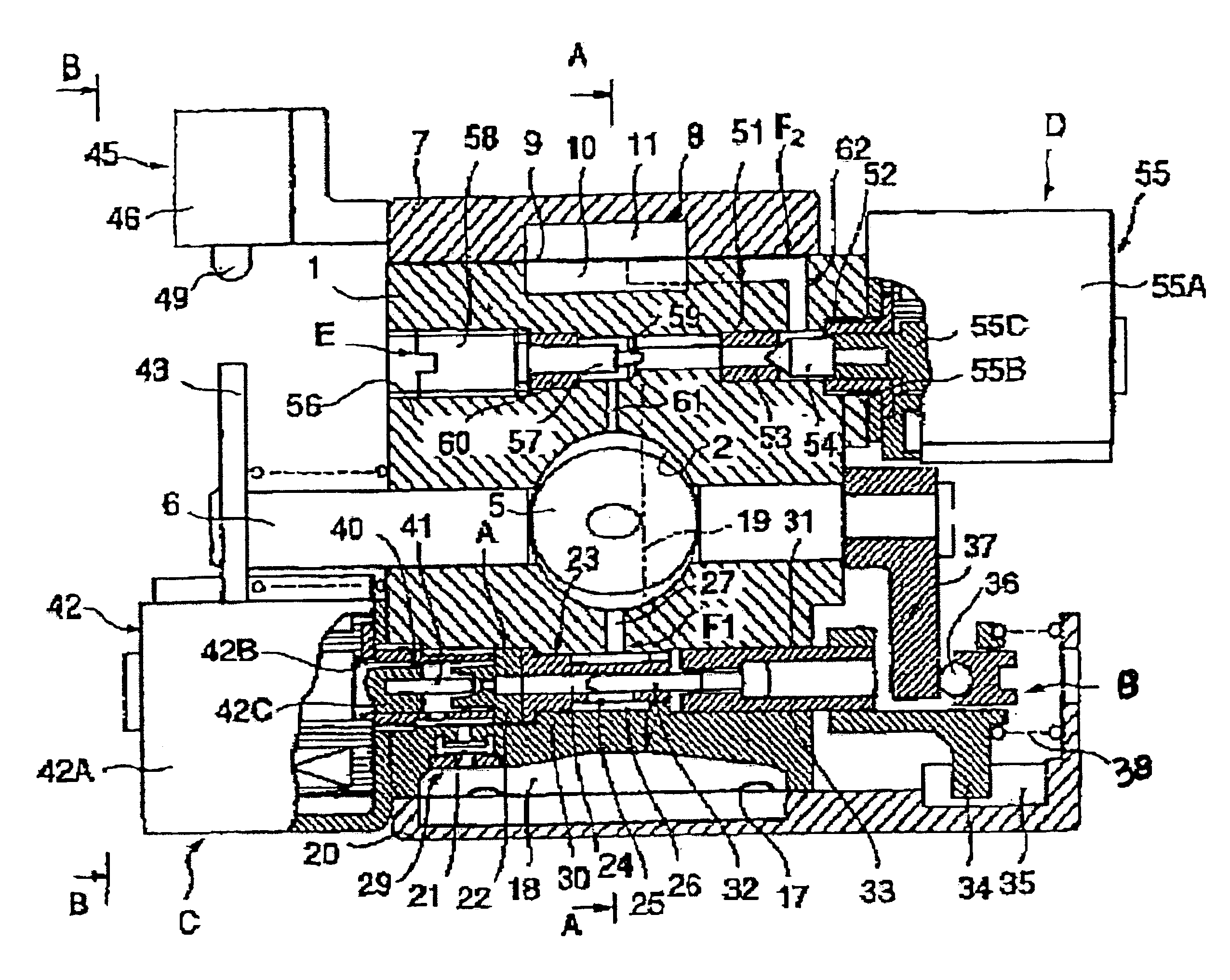
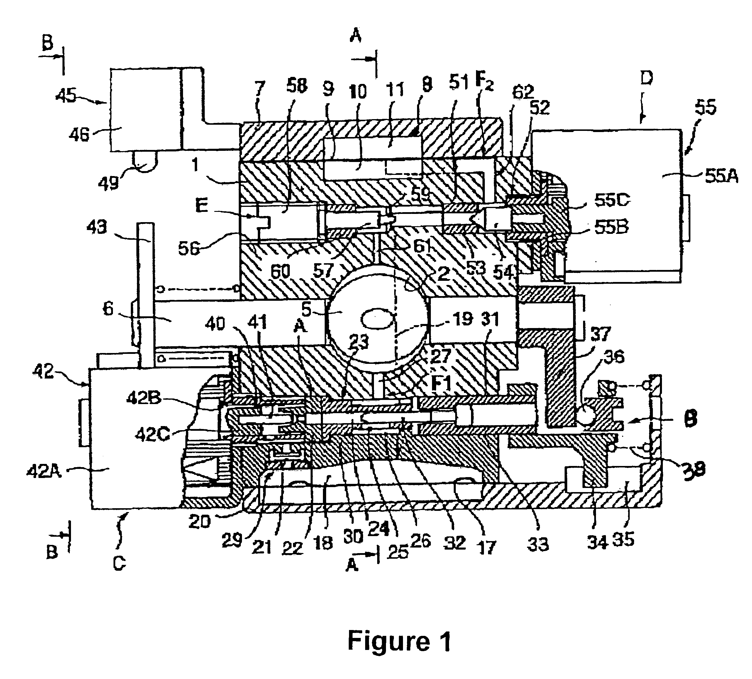
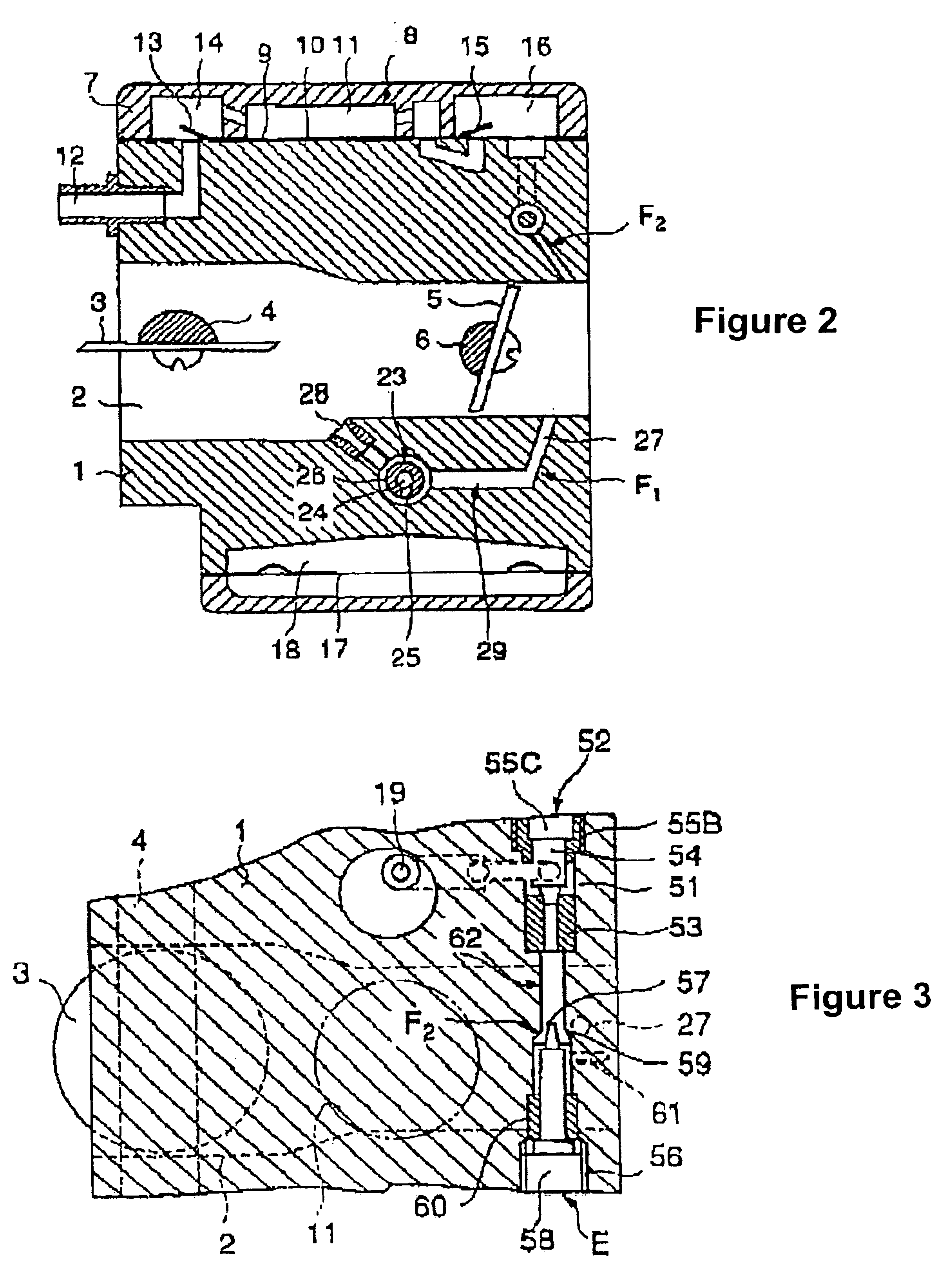
[0022]Describing the preferred embodiments with reference to the diagrams, FIGS. 1 to 5 are diagrams showing a structure to which the present invention has been applied, wherein a main body 1 has an air intake passage 2 extending in the lateral direction, a choke valve 3 is positioned in the inlet portion of this air intake passage 2, and a throttle valve 5 is positioned in the portion proximate to the exit. These are butterfly valves that are mounted on the choke valve stem 4 and the throttle valve stem 6, which are rotatably supported by the main body 1.

[0023]A pump cover 7 is overlaid on one surface of the main body 1, with a pump diaphragm 9 sandwiched therebetween. Depressions that are formed opposite each other in the main body 1 and the pump cover 7 on both sides of the pump diaphragm 9 respectively form a pulse chamber 10 connected to the engine crank case and a pump chamber 11 for taking in and discharging fuel. The fuel in the fuel tank that passes through a conduit, is di...


PUM

PropertyMeasurementUnit
Temperatureaaaaaaaaaa
Flow rateaaaaaaaaaa
Speedaaaaaaaaaa

Abstract

A carburetor is provided that supplies an appropriate amount of fuel at engine start-up and in a specific range of rotational speed, and allows stable engine operation at a target rotational speed. The carburetor comprises a first fuel system (F1) for metering fuel from the constant fuel chamber (18) with a metering needle (32) linked to a throttle valve (5), and delivering the fuel to an air intake passage (2); and a second fuel system (F2) for controlling fuel compressed by a fuel pump (8) with an electromagnetically driven control valve (52) and delivering the fuel to the air intake passage (2); by supplying pressured fuel controlled by the control valve (52) in a predetermined specific range of rotation and controlling the rotational speed during start-up and warm-up, a target rotational speed can be maintained.

Description

FIELD OF THE INVENTION[0001]The present invention relates to a carburetor for application in supplying fuel to general purpose engines, and more particularly to a carburetor that is capable of allowing stable engine operation across a broad range of operation from start-up to maximum load.BACKGROUND OF THE INVENTION[0002]The following devices are well known as carburetors that supply fuel to two-cycle or four-cycle general purpose engines: fixed-venturi carburetors that comprise a butterfly-type throttle valve and two fuel systems composed of a main system and a speed-reducing system as shown in Japanese Patent Application Laid-open No. 55-69748, and other publications; variable-venturi carburetors that comprise a cylindrical sliding throttle valve and a single fuel system in which the fuel delivery quantity is made variable by way of a metering needle as shown in Japanese Utility Model Publication No. 49-17682, and other publications; and carburetors that comprise a cylindrical rot...

Claims


Application Information

Patent Timeline
IPC IPC(8): F02M7/18F02M1/00F02M17/00F02M7/00F02M17/04F02M1/04F02M1/02F02M7/04
CPCF02M1/04F02M17/04F02M7/18Y10S261/74
Inventor NONAKA, TAKUMI
Owner ZAMA JAPAN
Why Eureka
Try Eureka